I'm gathering that you connected the n-c stator's two wire-leads directly to a full-wave rectifier-unit (with incorporated unknown regulator-type), thus of course ignoring the normal ground-connection at the stator, correct?
Correct...
It's too bad that you didn't take either a voltage or current reading from that 60-watt light, so that we could have then figured the wattage being produced at that RPM. That it was not fully brightened, only tells us that the light was drawing under 5-amps.
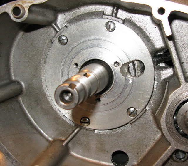
That's the beauty of a test fixture, ease of swapping hardware. I put the n-c alternator back on and got some hard numbers, used a generic rectifier block. Not sure how to take advantage of the chassis ground, I don't believe the rectifier uses it's case as anything but a heat sink but ran a wire from it to the stator backing plate anyway.
With a 55w light only it put out 10.6v and drew 4.3 amps. With the battery added, starting at 12.3v, the light brought it down to 11.8v and drew 4.6 amps, the n-c alternator obviously doesn't charge it at this voltage/rpm.
_ Which is of course expectable under 4000RPM.
Even the single phase kawi alternator will charge the battery with the light on at 14.6v drawing 5.5 amps and when run with the unregulated setup burned out the 60w light like a flash bulb at the same rpm the stock alternator couldn't get it to 11v.
I may try measuring the current draw of the drive motor to get some idea of what the relative force is to drive each alternator at a given load. I'm curious to see if the better regulating method on the 3 phase reg/rec's makes much difference once the battery is at full charge. One problem I'm having in keeping things consistent is that the battery gets a bit of a charge on each run so the draw isn't going to be the same on the next or previous run.
I could potentially 'borrow' a dc motor and variable speed controller from another piece of equipment to try higher speed testing but have no practical way of measuring rpm, so the results would be only applicable in comparing each alternator at a higher but unknown speed. Though it's possible there are differences in efficiency at various rpm for each unit, for most intents and purposes I think the 3450 rpm fixed speed gives me a reasonable baseline for apples to apples comparison.
One difference I noticed about the efficiency between the (newer) 1 phase and 3 phase is that the little electronic test leads I was using between the stator and rectifier were fine for 3 phase but melted when used on the 1 phase. I read an explanation for it somewhere and recall it saying that it goes beyond just spreading the load over one more wire.
__ Also, not knowing the manor of the regulator used, it may taint results. _ So, as long as your testing is kept under an hour, you need not employ any regulator for these tests of yours, (unless it's the regulator itself that you're testing) !
I suggest that you use only a plain full-way rectifier (known to be completely good!), so that you can more certainly trust the result-figures.
As long as I use the same regulator for all the alternators, the results should be relative. You can see that I need to regulate the newer stuff or it will cook everything.
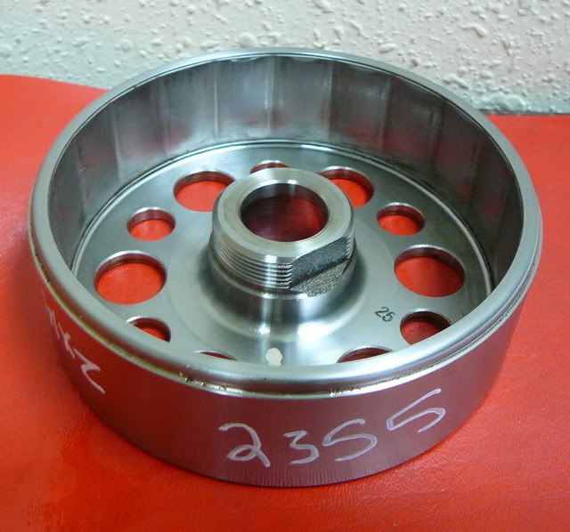
I only asked about the whereabouts of that Suzuki-rotor, as I much wonder if you could still compare it's magnet-layout with that of the n-c DUCATI-rotor.
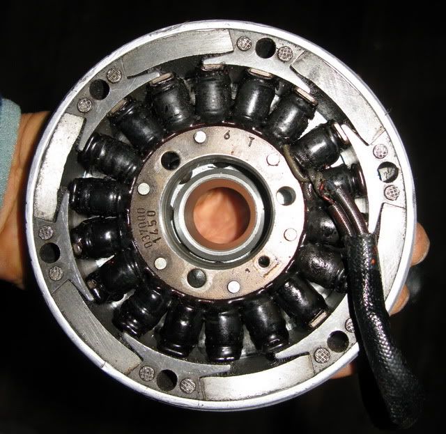
I don't know a lot about alternator design, just exercising some common sense when mixing components. The gs suzuki 3 phase alternator has 12 magnets/18 coils, the kz kawi 1 phase alternator has 12 magnets/12coils. They are both 93mm stators and the components still function when swapped with each other. Unlike the n-c layout, the magnets appear to be placed pretty much right next to each other. To obtain 3 phases I would guess the 18 coil stator is wired in 3 sets of 6 coils. I've noticed that some of the very newest stuff has 15 coils, must be 3 groups of 5(?).
The ( 1 phase) n-c alternator (also 93mm) has 6 magnets/6 (coils/positions, two unused). It now seems obvious that the n-c rotor doesn't work with the either of the newer stators because the magnets are so wide they simultaneously cover the space of two or three of the smaller size coils, canceling each out. I suppose it would be possible make them narrow enough by cutting the 'skirts' off of the cores between each magnet, don't think I'll do that though just to try it and ruin an otherwise sale-able item.
I wonder if a stator with 9 coils wired 3x3 would work as 3 phase?
Not even sure what's driving me on with this at this point as I already have 3 or 4 workable 'alternator alternatives', curiosity I guess... Next is ignitions...