Methods to Increase Power from N-C twin-wirelead Alternators

Ducati single cylinder motorcycle questions and discussions, all models. Ducati single cylinder motorcycle-related content only! Email subscription available.
Moderator: Morpheus

Moderator: ajleone

wcorey
Posts: 323
Joined: Sun Jan 31, 2010 1:50 am
Location: MA USA

Re: Methods to Increase Power from N-C twin-wirelead Alternators

Postby wcorey » Thu Oct 28, 2010 7:32 am

I'm gathering that you connected the n-c stator's two wire-leads directly to a full-wave rectifier-unit (with incorporated unknown regulator-type), thus of course ignoring the normal ground-connection at the stator, correct?


Correct...

It's too bad that you didn't take either a voltage or current reading from that 60-watt light, so that we could have then figured the wattage being produced at that RPM. That it was not fully brightened, only tells us that the light was drawing under 5-amps.


That's the beauty of a test fixture, ease of swapping hardware. I put the n-c alternator back on and got some hard numbers, used a generic rectifier block. Not sure how to take advantage of the chassis ground, I don't believe the rectifier uses it's case as anything but a heat sink but ran a wire from it to the stator backing plate anyway.
With a 55w light only it put out 10.6v and drew 4.3 amps. With the battery added, starting at 12.3v, the light brought it down to 11.8v and drew 4.6 amps, the n-c alternator obviously doesn't charge it at this voltage/rpm.

_ Which is of course expectable under 4000RPM.


Even the single phase kawi alternator will charge the battery with the light on at 14.6v drawing 5.5 amps and when run with the unregulated setup burned out the 60w light like a flash bulb at the same rpm the stock alternator couldn't get it to 11v.
I may try measuring the current draw of the drive motor to get some idea of what the relative force is to drive each alternator at a given load. I'm curious to see if the better regulating method on the 3 phase reg/rec's makes much difference once the battery is at full charge. One problem I'm having in keeping things consistent is that the battery gets a bit of a charge on each run so the draw isn't going to be the same on the next or previous run.
I could potentially 'borrow' a dc motor and variable speed controller from another piece of equipment to try higher speed testing but have no practical way of measuring rpm, so the results would be only applicable in comparing each alternator at a higher but unknown speed. Though it's possible there are differences in efficiency at various rpm for each unit, for most intents and purposes I think the 3450 rpm fixed speed gives me a reasonable baseline for apples to apples comparison.
One difference I noticed about the efficiency between the (newer) 1 phase and 3 phase is that the little electronic test leads I was using between the stator and rectifier were fine for 3 phase but melted when used on the 1 phase. I read an explanation for it somewhere and recall it saying that it goes beyond just spreading the load over one more wire.


__ Also, not knowing the manor of the regulator used, it may taint results. _ So, as long as your testing is kept under an hour, you need not employ any regulator for these tests of yours, (unless it's the regulator itself that you're testing) !
I suggest that you use only a plain full-way rectifier (known to be completely good!), so that you can more certainly trust the result-figures.


As long as I use the same regulator for all the alternators, the results should be relative. You can see that I need to regulate the newer stuff or it will cook everything.

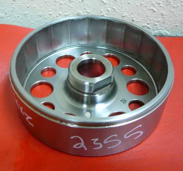
I only asked about the whereabouts of that Suzuki-rotor, as I much wonder if you could still compare it's magnet-layout with that of the n-c DUCATI-rotor.


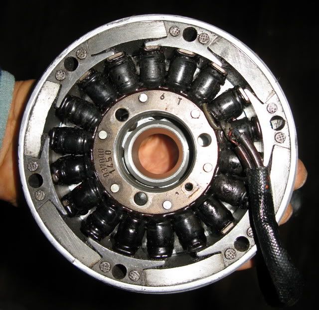
I don't know a lot about alternator design, just exercising some common sense when mixing components. The gs suzuki 3 phase alternator has 12 magnets/18 coils, the kz kawi 1 phase alternator has 12 magnets/12coils. They are both 93mm stators and the components still function when swapped with each other. Unlike the n-c layout, the magnets appear to be placed pretty much right next to each other. To obtain 3 phases I would guess the 18 coil stator is wired in 3 sets of 6 coils. I've noticed that some of the very newest stuff has 15 coils, must be 3 groups of 5(?).
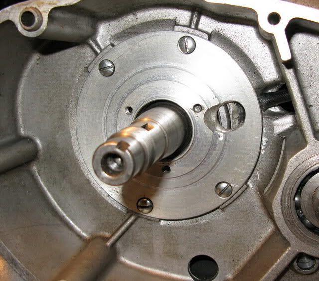
The ( 1 phase) n-c alternator (also 93mm) has 6 magnets/6 (coils/positions, two unused). It now seems obvious that the n-c rotor doesn't work with the either of the newer stators because the magnets are so wide they simultaneously cover the space of two or three of the smaller size coils, canceling each out. I suppose it would be possible make them narrow enough by cutting the 'skirts' off of the cores between each magnet, don't think I'll do that though just to try it and ruin an otherwise sale-able item.
I wonder if a stator with 9 coils wired 3x3 would work as 3 phase?

Not even sure what's driving me on with this at this point as I already have 3 or 4 workable 'alternator alternatives', curiosity I guess... Next is ignitions...
Image

Image

Image

DewCatTea-Bob
Posts: 2897
Joined: Sun Nov 01, 2009 10:53 am
Location: Near SE side of Lake Michigan

Interesting Alternate Alternator-Reseach by wcorey !

Postby DewCatTea-Bob » Fri Oct 29, 2010 1:32 am

" That's the beauty of a test fixture, ease of swapping hardware. "

____ And that's really great that you're taking further advantage of your set-up/project !
Just gave your post here a quick read-through and it's informative and also helps make clear everything you've written, to make good sense !


" I put the n-c alternator back on and got some hard numbers, used a generic rectifier block. "

____ That's great, thanks for that !


" Not sure how to take advantage of the chassis ground, I don't believe the rectifier uses it's case as anything but a heat sink but ran a wire from it to the stator backing plate anyway. "

____ You're right, that equivalent of a ground-connection for the rect.block & the grounded-stator, would have no intended electrical-function.
However, it seems you've been always running the stator's two separate power-windings in series,, yet there's a possible current-advantage by running the two rectified power-outputs in parallel. _ So it would be nice to try a comparison-test, by also trying the combined outputs of two separate rect.blocks, simultaneously FULL-wave rectifying both power-windings, so as to get their combined full-current. - (It's understood that this data would be less useful for 12-volt systems.)


" With a 55w light only it put out 10.6v and drew 4.3 amps. "

____ Thanks for that data ! _ Now we know that at the RPM of your drive-motor, the n-c alternator produces 46-watts.


" With the battery added, starting at 12.3v, the light brought it down to 11.8v and drew 4.6 amps, the n-c alternator obviously doesn't charge it at this voltage/rpm. "

____ Right, all it's output is doing is help prevent the battery from draining as fast as it otherwise would.


" I may try measuring the current draw of the drive motor to get some idea of what the relative force is to drive each alternator at a given load. I'm curious to see if the better regulating method on the 3 phase reg/rec's makes much difference once the battery is at full charge. "

____ That's all good-thinking and pretty interesting to learn of ! _ Hope you find the time, (ought the be more entertaining than watching most TV-programing).
__ It would also be interesting to compare the different regulator-units, to see if one unit causes any more drag/current-draw for your drive-motor, than another unit does.


" One problem I'm having in keeping things consistent is that the battery gets a bit of a charge on each run so the draw isn't going to be the same on the next or previous run. "

____ That's of course a good-point, and a major source of inconsistent readings !
I'd suggest substituting the battery, with a large-capacitor and a 'tail-light' *, connected in a parallel-circuit, so as to represent a charged-battery,, (*or else a 'brake-light', to represent a charging-battery).


" As long as I use the same regulator for all the alternators, the results should be relative. "

____ Yes that would normally seem to be true (at least with the old-type of electronic-regulators of days past, but I don't know anything about the V.reg-unit you're using, and I gather that some of the more modern units employ I.C-brains which don't always do their job in a consistent manor.


" You can see that I need to regulate the newer stuff or it will cook everything. "

____ Right, sorry about that ! _ I hadn't chosen my wording very well, as at the time, I was only thinking of protecting the battery (not a light) from the expected alt.power-output of any alt.stator which is small enough to still fit in the very same space as a DUCATI's,, and at that under 4000-RPM range.


" The gs suzuki 3 phase alternator has 12 magnets/18 coils, "

____ OH, well that then explains why it's stator didn't work for you ! _ I had assumed that it's rotor also had 6 magnet-poles, like the DUCATI-rotor's has.
So I was wrong to figure that stator had 3 sets of 6 coils each, so as to obtain the extra 2 phases (with the 6 magnetic-poles of the duke-rotor).
(Sure was much simpler back in the old-days!)


" the kz kawi 1 phase alternator has 12 magnets/12coils. "

____ If it was a 3-phase instead, it could then get-by with just 4 magnets.


" To obtain 3 phases I would guess the 18 coil stator is wired in 3 sets of 6 coils. "

____ That's what I had thought, until you reviewed that it's rotor had 12 instead of only 6 magnet-poles,, which would make for some kind of square-dance, (without either 6 or 18 magnets).
That it had more than 6 (other than 18) magnets means that each & every coil is not wired/wound exactly the same as it's neighboring coil and/or the stator has it's 3 sets of windings wound & arranged in a matter which requires magnetic-pole flipping every 30-degrees (instead of just every 60). _ So it's got to be wound much more complexly than just the same as three separate 6-pole windings spaced-apart by 20-degrees, (which could work with just the 6 magnet-poles).


" I've noticed that some of the very newest stuff has 15 coils, must be 3 groups of 5(?). "

____ Right, and that would space-apart the coils by 24-degrees,
(and probably use 10-magnets?).


" It now seems obvious that the n-c rotor doesn't work with the either of the newer stators because the magnets are so wide they simultaneously cover the space of two or three of the smaller size coils, canceling each out. "

____ Well that's only because the neighboring coils must not be wound/wired and arranged in successive phased sets, or else it would actually be fine for that width-overlap to occur.


" I wonder if a stator with 9 coils wired 3x3 would work as 3 phase? "

____ That would be quite a puzzle to work-out, since the rotor has to have an EVEN number of poles,, but I assume that 6 magnet-poles could possibly work, so long as the coils are wound & arranged in that tricky set-up -(that makes the 1.5:1 square-dance, between the coils & magnets).


" Not even sure what's driving me on with this at this point as I already have 3 or 4 workable 'alternator alternatives', "

____ Could you please separately list each one of those, in order of easiest for others to duplicate ?


Hopeful-Cheers,
-Bob
PLEASE NOTE... If this-post is not-yet signed-off with '-Bob', then I'm still in the process of completing it,, and if not also included with 'DCT' near bottom as well, then I may edit this post's wording at a later time. - Dct.Bob

grapes
Posts: 17
Joined: Sat Oct 16, 2010 2:47 am

Re: Methods to Increase Power from N-C twin-wirelead Alternators

Postby grapes » Fri Oct 29, 2010 3:11 am

Dew Cat Tee Bob

Part #1 I have made a model of and I fully under stand it.
Part #2 I believe the two remaining neg posts on the rectifiers, could be used one for the battery
The remaining one(+) could then be used to run a second battery ,but pos ground or to a British battery eliminator.
this is where you stop without details.
How do you tell which one is neg, and which is pos? Start the motor and using a voltmeter to determine which is which?
Does the neg one attach to the neg of the battery? and the other (pos) attach to the Britt eliminator.
I like this system, I need the last details,as I'm a house electrician, not an alternator electrician.Please understand
I like what you have accomplished, You must understand I need the last details Thank you so much Capt Paul.

DewCatTea-Bob
Posts: 2897
Joined: Sun Nov 01, 2009 10:53 am
Location: Near SE side of Lake Michigan

Possible Methods for Wiring Dual-Charging System's Outputs

Postby DewCatTea-Bob » Fri Oct 29, 2010 6:57 am

" this is where you stop without details. "

____ Sure-thing, Paul... Always happy to provide additional direction !
I'm not sure where you've been reading, so it would help if you reminded me which page & post you're having further question from. ...
I'm guessing that I didn't offer further detail because at that point, there became too many options (for individuals to possibly go-with), for me to continue-on explaining all the various details of each & every possibility,, and figured that it would only be worth-while to continue any further, only after somebody presented their particular set of circumstances, (which I expect you now wish to do?).


" How do you tell which one is neg, and which is pos? "

____ Okay, I'm assuming that you have the circumstance where your twin-wirelead alternator is left unaltered within a complete motor, and yet you wish to still make use of 100% (rather than the stock 50%) of the available alt.power-juice,, with the use of two full-wave rect.blocks. _ Thus those two rect.blocks provide 4 separate power-outputs, of which are to be circuited through your loads to 'Ground',, and this thus brings us to the details of how to make use of all those power-outputs, (I gather you'd like to know).
__ Assuming that that's the case, I should point-out that a regular electrical-system doesn't have a use for all these power-outputs ! _ It is however a neat way to obtain two separate & adequately strong power-systems, to isolate a DC ignition-system from your DC lighting system.
To obtain the 4 power-outputs -(2 Positive & 2 Negative, [with respect to Ground] ), ya connect-up two separate full-wave bridge-blocks to the two alt.wire-leads... Specifically, one Yellow wire-lead to BOTH of the two AC-inputs of the First Bridge-Block, so as to then obtain a (Standard) Positive-output from the B.Block's Plus-terminal, as well as a (nonStandard) Negative-output from it's Minus-terminal, (either output-polarity being reactive with 'Ground', as is intended).
The exact same, is the identical case also for the Second B.Block with the other/opposite Yellow alt.wire-lead, as well !
__ As for which terminal is which on YOUR B.Blocks,
if they are not marked with at least a '+' mark indicating their Plus-terminal, then they should've came with instructions that tell which terminal is which.


" Does the neg one attach to the neg of the battery? and the other (pos) attach to the Britt eliminator. "

____ Since you needed to ask this, must mean that you likely hadn't properly understood my previously presented details, repeated up-above (in different wording), (or maybe your presented wording has simply not accurately represented your actual inquiry?).
__ With the four power-outputs, only one is needed to keep the battery charged & run an ignition-system (IF you so choose) ! _ The other 3 power-outputs can be used as you find need for them. _ As there are a number of ways to make use of them !
__ Since you seem to intend to have both a battery as well as a battery-eliminator, then I'd suggest that one of the Positive-outputs be (indirectly) connected to the POS.post of the battery, and the other Positive-output be connected to a switch that's to be turned-on for only when the battery-powered lights are turned-on.
And I suggest that BOTH of the Negative-outputs be connected to your bat.eliminator for running the ignition & brake-light. _ As that unit will charge-up & save all power-juice supplied to it that's not used by your ignition-system, thus it won't be wasting any power & help overheat the alt-stator.
Depending on the complexity of your particular bat.elim-unit, you may need a ballast-resistor for your ign.coil.
____ If you still have more questions, then please be specific. _ As I don't mind explaining in further-detailed details.
__ The complete electrical-system I wired-up for my very-own n-c DUKE (using this dual-charging system) was very complex, and really neat as well (in my opinion) but, I doubt that anyone would ever care to wire-up everything as I had done. _ And since others may choose to do things a bit differently, I haven't bothered to detail all of the wiring-connections that did. _ But if you like, I could do that if you wish to wait for me to get it all written-down.


Fun-Cheers,
DCT-Bob
PLEASE NOTE... If this-post is not-yet signed-off with '-Bob', then I'm still in the process of completing it,, and if not also included with 'DCT' near bottom as well, then I may edit this post's wording at a later time. - Dct.Bob

grapes
Posts: 17
Joined: Sat Oct 16, 2010 2:47 am

Re: Methods to Increase Power from N-C twin-wirelead Alternators

Postby grapes » Sat Oct 30, 2010 2:58 am

Dew Cat Tee Bob;
I'm talking about the very first opening thread of this thread, that you start off by saying this thread has been re edited for clarity and more info.
Then Part #1 Is a piece of great writing that I completely under stand, and made a model of part #1
Now part #2 tells of utilizing the two neg connectors that are left unused, and one is neg grounded, But the other is pos ground as in Britt bikes One can be used to chg the battery, but the pos grounded one could run the ignition via Britt bike battery eliminator.
Now all I'm asking is, how to determine the polarity of the of the two, and how to wire the extra battery supply, and exactly how to wire the Britt bike eliminator? Because that's what I want to use. Thank you for your patience with me.Capt Paul

DewCatTea-Bob
Posts: 2897
Joined: Sun Nov 01, 2009 10:53 am
Location: Near SE side of Lake Michigan

Re: Terminal-Polarities of Bridge-Blocks & Bat.Eliminators

Postby DewCatTea-Bob » Sat Oct 30, 2010 8:50 am

" Now all I'm asking is, how to determine the polarity of the of the two, and how to wire the extra battery supply, and exactly how to wire the Britt bike eliminator? "

____ Okay, it seems you understand what's intended so far as what's available with the use of two separate bridge-rect.blocks. _ But that you don't yet realize how to tell which of the 4 power-outputs are POSitive and which are NEGative (in relation to Ground), without actually testing them all with a meter.
Well that's determined by differing means, depending on the manufacturer of your bridge-blocks... Normally just one of the B.Block's four 90-degree corners is flattened with a 45-degree slash-cut, so as to indicate that the terminal nearest to that particular corner, is the POSitive-output of it's Bridge-rectifier. _ Cuz once that's established, it's then supposed to be understood that the OPPOSITE-corner's terminal is the NEGative-output, and the other two corner's terminals are thus for the AC-input !
__ Now each of your two B.Blocks will of course have one NEGative & one POSitive power-output !
And you already understand what to do with the std/normal (DUCATI-like) positive-outputs, but wish more guidance with the (Brit-bike) like NEGATIVE-outputs.
__ Well, it's really up to you of course, however you could (for instance) use a black 16Ga-wire to (indirectly) connect the NEG.output from B.Block #2, to the NEG.post of a (small)- battery (which of course then must have it's POS.post connected to Ground). _ And you could use a black&white 16Ga-wire to connect the NEG.output from B.Block #1, to the NEG.input of a Brit-bike type of battery-eliminator. _ Such battery-eliminators are not always quite the same, and thus you should wire it as directed (for positive ground systems). _ If you have one of the cheap/simple single-capacitor types, it's NEG.input is also it's NEG.output (and it's [positive] casing is grounded). _ Such a simple BAT.elim-capacitor, is then directly connected to your key-switch providing that it's the type of switch which makes/brakes (at least) two SEPARATE circuits ! _ The stock Monza key-switch is such a twin-circuit type key-switch. _ Therefore, one/half of it's twin On/Off switch is needed for the positive-to-ground circuits,, and the other-half (completely separate) On/Off-switch is needed for your NEGative-to-ground circuits. _ Both of the two different n-c Monza key-switches are usable for my dual-charging systems.
____ I don't much care for single-cap type BAT.elim-units, and I've mentioned elsewhere about how to make better B.E-units using two capacitors of different sizes,, but also, two caps of the same size could also be used together but, with one being connected in series with a low-impedance inductor.
__ If you don't think yours is such a cheap type of B.E-unit, then please post a pic of it, (for possible better advice about wiring it up).


Hopeful-Cheers,
DCT-Bob
PLEASE NOTE... If this-post is not-yet signed-off with '-Bob', then I'm still in the process of completing it,, and if not also included with 'DCT' near bottom as well, then I may edit this post's wording at a later time. - Dct.Bob

grapes
Posts: 17
Joined: Sat Oct 16, 2010 2:47 am

Re: Methods to Increase Power from N-C twin-wirelead Alternators

Postby grapes » Sun Oct 31, 2010 11:48 pm

Dew Cat Tee Bob;

I'm referring to your post March 2nd of this thread,the first thread Intro I've edited this to correct and make the info correct.
Part 1 I have two bridge blocks I'll call block A, and block B, with the 2 yellow wires from the 40w Monza alt.one yellow wire to the a/c terminal and jumped to 2nd a/c terminal. The 2nd yellow wire, to block "B" a/c terminal jumped to the other a/c terminal.
Then a red wire from pos terminal block "A" to the key switch power battery.
Then a wire wire from pos terminal to block "B" to toggle switch to headlights.
Now we have a neg terminal left from each block left unused
Where does "A" block neg connect to? Where does "B" neg connect to?
One to Britt battery eliminator? The other to??????
Please help me finish this project Uncle Bob, Capt Paul

DewCatTea-Bob
Posts: 2897
Joined: Sun Nov 01, 2009 10:53 am
Location: Near SE side of Lake Michigan

Wiring Choices for the Dual-Charging System

Postby DewCatTea-Bob » Mon Nov 01, 2010 2:06 am

" I have two bridge blocks I'll call block A, and block B, with the 2 yellow wires from the 40w Monza alt. "

____ I understand, and I recall that YOUR '40-watt' alternator is the early 4-speed Monza-type -(which has two identical power-coils).
This is the very same type of alternator that I first found the need to modify the stock charging-system of,, since I then realized that it's heavy-black rectifier-box only used two power-diodes to HALF-wave rectify each of the two alt.power-coils.
__ The only difference is that when I first did this modification/improvement in total alt.power-output to my (expanded) charging-system, I then used only two extra diodes... The only reason for why we are now using two bridge-blocks (instead of just two pairs of diodes) is because the handy modern bridge-blocks are cheap & easy to mount !!


" one yellow wire to the a/c terminal and jumped to 2nd a/c terminal. "

____ That's correct, the 1st alt.power-coil's Yellow wire-lead is connected to BOTH of block-A's AC-input terminals, (only for the purpose of spreading-out the current-juice across two of the block's included diodes, thus avoid wasting the fact that the block contains an otherwise unneeded extra diode, which also thus allows the use of a block that's rated to handle half as much amperage as otherwise would be needed, for the required diodes).


" The 2nd yellow wire, to block "B" a/c terminal jumped to the other a/c terminal. "

____ Right, (as just the same as for the 1st alt.wire-lead & block-A) !


" Then a red wire from pos terminal block "A" to the key switch power battery. "

____ Right... rather than have your connecting-wire, (which ought to be orange), run DIRECTLY to your (NEG.grounded)- battery's POS.post/terminal, it should detour (from B.Block-A's POS.output) to your key-switch where it will be isolated from the battery & your load-system (until key switched on). - (That's with the preferred use of a w-c type 3-pole key-switch,, with an original Monza-type switch, it's not possible to have a 3rd-pole for isolating the battery & the charging-output from each other with the key-switch turned-off.)


" Then a wire wire from pos terminal to block "B" to toggle switch to headlights. "

____ Typos aside, that's right... except, (like the 3-pole key-switch), your lighting toggle-switch should have (at least) three poles... That's one terminal for the connecting-wire from B.Block-B, one terminal for the wire-connection from the output of the key-switch, and one terminal for the toggle-switch's output to your lighting-load.
(I'll be glad to elaborate about any of this stuff, if you don't already realize the deal concerning switch-types.)


" Now we have a neg terminal left from each block left unused "

____ Correct, those two separate NEG.terminals each have pulsating-DC power-juice available but, it's NEGATIVE towards ground, (just like the Brit-bikes employed) ! _ This is the part of the alt.power that Ducati's systems don't make any use of at all.


" Where does "A" block neg connect to? "

____ What the neg.terminal of either bridge-block is connected to, has already been suggested previously... It's up to you as to exactly what you'd like to use the extra available power-juice for. _ (I have chosen to have it charge an extra battery (that's positive grounded!),, and I've also used it to charge capacitors for lights & ignition.)


" Where does "B" neg connect to? "

____ Ditto, as above, also for the neg.terminal on 'B.Block-B', as well.
Either or both negative-outputs from the two bridge-blocks can be connected to a capacitor or a battery (with POS.post grounded). _ Or, one neg.output from one b.block to a battery, and the other to a capacitor. _ It's up to you (and the electrical-system you wish to wire-up).


" One to Britt battery eliminator? "

____ If your Brit-bike type of battery-eliminator is to be used to run your ignition-system, then you'll need to connect both neg.outputs from the pair of b.blocks so as to be sure that your ign.system gets the particular pulse of (alternator/diode supplied) DC which just happens to be 'in-time' with the ign.spark.
Otherwise you may or may not pick the correct neg-output that includes a DC power-pulse which will fully-assist at powering the ignition,
and if you choose the neg.output that's dead at the very time when the ign.spark is to be generated, then your ignition-system will have to depend on just the stored-charge within the capacitor, which may be too week at starting-RPM.
__ You see, each neg.terminal of each b.block will output 4 negative power-pulses per ign.spark,, only thing is, when one b.block is offering one of it's neg.pulses, the other b.block is only putting-out a pos.pulse, and therefore it's neg.terminal is 'dead' at that same instant (when the other b.block's neg.terminal is live with a neg.pulse). _ So you need to choose the b.block which is offering a neg.pulse at the same instant when the ign.points open. _ As one b.block will be doing so while the other is then dead.
It's possible to find-out which is which, by disconnecting the capacitor while the engine is running... As the correct pulsating-DC output will keep the ign.spark running, while the wrong choice will let the spark die (& kill the engine).
__ Either neg.output offers more than sufficient power-juice to run the ignition, since both alternator/diode outputs each supply 4 DC-pulses per 4stroke-cycle to charge the B.E-cap, and the ignition-spark only requires the juice of about one of those DC-pulses.


" The other to?????? "

____ The other NEG.output's own 4 neg.power-pulses (per Otto-cycle) could also go into charging the same (or another) B.E-cap,, or another battery. _ (I've done both set-ups on past projects, and when I chose to use TWO batteries, they were about: 2 x 3 x 5" in size, each.)

____ Let me know if you still want even more details ironed-out.
I think it would be a good-idea to let me know exactly what ideas you're considering for your particular wiring-plans, so that I might offer any bits of advice.


Hopeful-Cheers,
DCT-Bob
PLEASE NOTE... If this-post is not-yet signed-off with '-Bob', then I'm still in the process of completing it,, and if not also included with 'DCT' near bottom as well, then I may edit this post's wording at a later time. - Dct.Bob

grapes
Posts: 17
Joined: Sat Oct 16, 2010 2:47 am

Re: Methods to Increase Power from N-C twin-wirelead Alternators

Postby grapes » Sun Nov 07, 2010 4:40 am

Dew Cat Tee Bob,

The bridge rectifiers used for the projects to improve ducati charging and lighting are labeled,GBPC25005,from Radio Shack.
I found one in a shop crane, marked, CBR25-040. Do these numbers denote their value? Or their limitations?
Do these numbers tell you their minimum-maximum range of uses? How do you read them? Just curious>
Capt Paul

DewCatTea-Bob
Posts: 2897
Joined: Sun Nov 01, 2009 10:53 am
Location: Near SE side of Lake Michigan

I.D.numbered Bridge-block's Spec.Ratings

Postby DewCatTea-Bob » Sun Nov 07, 2010 12:40 pm

" The bridge rectifiers used for the projects to improve ducati charging and lighting are labeled,GBPC25005,from Radio Shack. "

____ I myself didn't recommend that number, as the values for that model are 25-amp & 50-volt, while I recommend (at least) 6-amp & 100-PeakInverseVolts. _ (Keep in mind that since your rectifier-circuits employ two diodes working in parallel, that thus doubles the amperage-rating (given for the b.blocks), thus your chosen b.blocks can each pass up to 50-amps (each) for your charging-system ! _ Yet can still only deal with just 50PIV.
(I'd still use those... I'd just add an extra power-diode (rated-at at-least 10a/25piv), in series with the battery.)


" I found one in a shop crane, marked, CBR25-040. Do these numbers denote their value? "

____ Not always, as those are just Mft.part/model-No.s and can't be counted-on to include part-specs. _ So ya have to go to the manufacturer to get the spec.figures for each part-model, in order to be sure. _ (I believe that model-number is obsolete anyhow.)


____ Hope you've noticed that I had added some extra info to my two previous posts (above, in this thread).
__ Even if you think you're all clear on exactly how all the involved wiring should be done-up, we should still go-over it all.
Are you drawing-up any wiring-scheme for yourself ?


DUKE-Cheers,
-Bob
PLEASE NOTE... If this-post is not-yet signed-off with '-Bob', then I'm still in the process of completing it,, and if not also included with 'DCT' near bottom as well, then I may edit this post's wording at a later time. - Dct.Bob


Return to “Ducati Singles Main Discussions (& How to Join)”

Who is online

Users browsing this forum: No registered users and 46 guests