Help with wiring please

Ducati single cylinder motorcycle questions and discussions, all models. Ducati single cylinder motorcycle-related content only! Email subscription available.
Moderator: Morpheus

Moderator: ajleone

ducwiz
Posts: 604
Joined: Tue May 22, 2012 12:52 pm
Location: near Frankfurt, Germany

Re: Help with wiring please

Postby ducwiz » Mon May 28, 2012 12:21 pm

@Jordan

This works indeed, because the outputs of the 2 windings are in anti-phase polarity, that is series connected.
For those who are eqipped with a multimeter: Disconnect the alternator from regulator or rectifier, connect meter on open wire ends - Running the engine at constant revs, you can measure an AC voltage between each winding end and the center tap, but twice this value between both ends!
If one intends to connect them in parallel, they must be re-connected in co-phase manner; in this case you would not measure any voltage between the two winding ends, but only between center tap and each end.
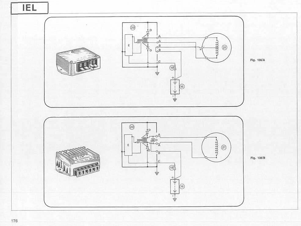
The shop manual of the 860 GT explains the basic difference between 2wire and 3wire stators/regulators. We have a 3wire alternator with the center tap (marked "+") grounded in the old singles, which in turn requires a special regulator version.

Image

Btw, a serial connection basically results on higher voltage at lower current, a parallel connection vice-versa.

@lloydy1

The number I quoted is stamped an the original regulator of the later singles like MkIII or Scrambler.
-> original type on ebay: http://www.ebay.ca/itm/ws/eBayISAPI.dll?ViewItem&item=190567756743&clk_rvr_id=347349960053&item=190567756743&lgeo=1&vectorid=229529
This is not available as a new sparepart anymore, but there seem to be replicas or substitutes (only powerdynamo tested by me):

trusty german company:
regulator/rectifier w/ battery: http://www.powerdynamo.biz/eng/parts/dcreg.htm
regulator/rectifier w/o battery: http://www.powerdynamo.biz/eng/parts/7036reg.htm
complete kit: http://www.powerdynamo.biz/eng/systems/7247/7247main.htm

down under:
http://www.roadandrace.com.au/electrics.htm
http://www.smallcoilrewinds.com.au/services/services.html
http://www.widecase.com/electrical-equipment-ie/alternator/prod_286.html

british Electrex company:
rectifier/regulator: http://www.electrexworld.co.uk/acatalog/Online_Catalogue_Regulator_Rectifier_206.html
regulator only: http://www.electrexworld.co.uk/acatalog/Online_Catalogue_Regulators_180.html
complete kits: http://www.electrexworld.co.uk/acatalog/Online_Catalogue_Stator_Kits_424.html

??: http://www.guzzino.com/6vsiphrere.html

DIY:
http://home.comcast.net/~loudgpz/GPZweb ... lator.html
http://home.comcast.net/~loudgpz/GPZweb ... Field.html

Hans

lloydy1
Posts: 75
Joined: Sun Apr 15, 2012 2:37 am

Re: Help with wiring please

Postby lloydy1 » Mon May 28, 2012 4:48 pm

Hi Hans, Sorry if I am a little slow, but what do you mean by the center tap? :oops:

I must say I appreciate all your help in this matter.

Cheers, Dave

Jordan
Posts: 1473
Joined: Fri Dec 24, 2010 11:29 am

Re: Help with wiring please

Postby Jordan » Tue May 29, 2012 2:29 am

Thanks Hans,
I guess you've tried it.
Without testing, I wondered about:
- polarity of the windings (that is, are the wire turns in the same direction for both legs of the centre tap alternator.
- whether both legs are induced by different (and possibly reversed to each other) magnets in the rotor.

Jordan

wcorey
Posts: 323
Joined: Sun Jan 31, 2010 1:50 am
Location: MA USA

Re: Help with wiring please

Postby wcorey » Tue May 29, 2012 3:05 am

but what do you mean by the center tap?


The two coil wires that are combined and soldered/grounded to the little tab on the stator core are what is being referred to as a 'center tap', as would be typical to find on a transformer.

Read further at your own risk, lol.

Why they are configured like that is because...;

(to save time I cut some of this from one of my posts in an older thread related to this subject, n-c alternator modifications: discussion and testing, viewtopic.php?f=3&t=556&start=350)

You'll notice that each coil has four wires emanating from it. This is due to the n-c stator coils being wound in a unique scheme that has two separate windings on each coil bobbin, an inner and an outer. There are two larger coils wound counter-clockwise and two smaller coils wound clockwise that alternate large/small/large/small around the stator. One of the windings on each coil bobbin is connected in series to it's counterpart on the next, creating two individual sets of 4 windings, one set all the ‘inners’, the other all the ‘outers’.
The two sets are connected at one end and grounded to the stator core, the other ends are the two output wires that go to the stock R/R.

The stock n-c rectifier/regulator (R/R) then half-wave rectifies each of the alternators two winding sets (in parallel with each other). This can be called dual half-wave rectification, which in this case is a type of full-wave (F/W), sort of…(½ + ½ = 1) but still only (in theory) taps half of the available power.

Many various schemes can be utilized to gain additional power from the stock alt. One simple way is in enabling use of a generic F/W bridged rectifier (or a more 'typical/standard' F/W R/R) by creating one series circuit out of the two winding sets, to accomplish this the grounded ends of the two winding sets ('center tap') need to be lifted/isolated. This defeats the original parallel type arrangement and creates a series circuit through/including both sets, though a side affect is that it doubles the resistance, resulting in an impedance mismatch with the load. While this is somewhat negated by the battery, the increase in working impedance in turn decreases the level of output to somewhat more than the stock configuration but nowhere near the doubling that would otherwise be expected.

If the grounded ends are lifted/separated and individual output wires are attached (resulting in 4 output wires total), then each winding set can be individually F/W rectified and so the current path (and resistance) is cut back in half. The outputs of the rectifiers can be combined, kept separate and/or switched in or out of use in various combinations. Wiring the stator in this way would enable ' switch-boarding' to achieve multiple schemes and leave many options open for future use (like if you later decide to run a high output headlight) without the need to access the stator in the the motor.

All that said, the load requirements of your system without a headlight are so minimal that pretty much any way you go will provide more than adequate output/charging. In this case I'd likely forgo a battery and just run a 'battery eliminator' cap in it's place (unless a stock R/R is used which I think needs a battery to function properly).

Sorry if this just further confuses things rather than clears them up but there really isn't just one obvious answer...

Without testing, I wondered about:
- polarity of the windings (that is, are the wire turns in the same direction for both legs of the centre tap alternator.
- whether both legs are induced by different (and possibly reversed to each other) magnets in the rotor.


The polarity is wired/wound to be opposite on each set of windings. The magnets on the rotor alternate north/south as on all alternators but since each coil bobbin has the two individual windings in opposite polarity, when a magnet passes over a coil, different polarities are induced by each winding.
Something like that anyway...

Bill

graeme
Posts: 1006
Joined: Sun Mar 25, 2012 12:00 am
Location: Tasmania Australia

Re: Help with wiring please

Postby graeme » Tue May 29, 2012 6:20 am

Electrickery !

ecurbruce
Posts: 313
Joined: Fri Apr 01, 2011 12:43 am
Location: Hurricane mills TN

Re: Help with wiring please

Postby ecurbruce » Tue May 29, 2012 4:23 pm

Bill,

What a good summary of the situation inside that alternator, you have a way with words at a useable level.(I still think you should write that article).

So, what about those four wires exiting the engine case, your readers may want to know where to put them?
Anyway, good work as always,

Lurking,
Bruce.

lloydy1
Posts: 75
Joined: Sun Apr 15, 2012 2:37 am

Re: Help with wiring please

Postby lloydy1 » Tue May 29, 2012 6:50 pm

Hi Bill,

Thanks you for that explanation which does simplify it some what.

I take it that the reason behind this alteration to the original alternator is because of what R/R are available today and for it to work affectively this mod is required?

Thanks, Dave

DewCatTea-Bob
Posts: 2897
Joined: Sun Nov 01, 2009 10:53 am
Location: Near SE side of Lake Michigan

Most SUITABLE/simple Charging-system !

Postby DewCatTea-Bob » Wed May 30, 2012 11:00 am

____ Sorry Dave, I've been off-line for the past few days and have thus missed this thread,, which was too-bad cuz I'm your TOP-expert on the kind of stuff you're asking about ! ...
__ You have the odd 60w.alt with the quite rare black & red alt.wire-leads, (as opposed to the regular twin yellow wire-leads).
In either case, one of them will run the ign.system while the other won't (due to alt.rotor-timing) ! _ Which is why the pair of alt.wire-leads really ought not be the same color.
__ Since you only wish to just merely run your ignition and keep the battery charged, what you thus-then need to do merely requires only the simplest of charging-systems ! ...
You ought thus-then ignore ONE of the alt.wire-leads, and simply use a single diode-rectifier unit (of 6 to 10 amp capacity) on the remaining alt.wire-lead, with the diode's positive-output connected to the battery's plus-terminal.
This simple setup will easily power the ignition and keep the battery charged, (during normal riding RPM), even if the brake-light is always remaining lit-up. _ However, (depending on the battery), leaving the horn or headlight turned-on, will soon run-down the battery and then prevent sufficient power to continue running the ignition.
Either alt.wire-lead will do your expected job, however only ONE in particular (of the two) will keep your ignition running even if the battery becomes discharged !
____ Sorry I don't have time now to include more details on this simplest of schemes, except to add that in this case, a voltage-regulator ought not be needed so long as your chosen battery is not too small !
__ I could also of-course direct you best on any of the other many schemes to go with here but, they're ALL over-kill for your particular needs !

____ I just had to read-through this thread BRIEFLY, and noted that others had referenced your stator as having a "center tap" ... but the actual arrangement is not ACTUALLY a REAL 'center-tap' (as transformers often employ),, but rather, that common-connection is actually just a 'common' -(a coined-short for: common-point/path) ! _ Cuz there are two SEPARATE alt.stator-windings (rather than one continuous-winding with a 'tap') ! - (Yes, I'M a stickler for exact-detail !)
__ The reason for understanding why the n-c alt.stator's ground-path shouldn't really be thought-of as both a 'common' AND a 'center-tap' as well, is because in the case of an actual "center-tap", the 3rd-wire 'tap' is placed (anywhere) within the terminal-ends of a single continuous winding (which has all it's turns uniformly wound in the same direction),, whereas (conversely) in the case of Ducati's two stator-windings, one winding is wound in opposition to the other's, and also since the end-tips between the two windings are not uncut from one-another, as well,, it's thus-then quite a great stretch to conclude the two stator-windings as being just one center-tapped winding !!


Dukaddy-DUKEs,
-Bob
PLEASE NOTE... If this-post is not-yet signed-off with '-Bob', then I'm still in the process of completing it,, and if not also included with 'DCT' near bottom as well, then I may edit this post's wording at a later time. - Dct.Bob

lloydy1
Posts: 75
Joined: Sun Apr 15, 2012 2:37 am

Re: Help with wiring please

Postby lloydy1 » Wed May 30, 2012 2:28 pm

Hi Bob,

Thank you for your input on this, it sounds a lot easier now that I haven't got to solder and unsolder wires etc, as I said in my previous messages I am a novice when it comes to the electrical side of things,

Cheers, Dave.

P.S. Can I thank everyone for there input on this thread. :)

wcorey
Posts: 323
Joined: Sun Jan 31, 2010 1:50 am
Location: MA USA

Re: Help with wiring please

Postby wcorey » Thu May 31, 2012 1:07 am

DUCATI had issued an instructional paper how to modify the stator for using with the new electronic type marked 34.41.06.


Interesting, I guess that must be where that mod originated, I had previously assumed it was something someone figured out that was just being passed around over the years through Ducati enthusiast circles. Always a great thing to have fresh input here on the list.


(I still think you should write that article).


Bruce, good to see you pop your head up once in a while.

While I would have very much liked to conclude that project, I just had too many unanswered questions to continue effectively and the momentum has eroded. As you remember, everyone got pretty burnt out on it and entirely abandoned ship, I would guess that still no one wants to jump down that rabbit hole again any time soon. I just don't have the capacity do it completely on my own.

My immediate interest waned as I put the R/T project on hold over the winter and my time got taken up by other things, I'm sure everyone knows how that goes. Been cutting a lot of wood this year so consequently got caught up in hopping up chainsaws, fairly cheap hobby as a saw can be significantly modded without the cost of additional parts and can be taken down and re-assembled multiple times in just hours. And you don't have to register/insure 'em (yet).

So, what about those four wires exiting the engine case, your readers may want to know where to put them?


Your opening yourself up to some off color comments on that one... :lol:
You know as well as I do that would require a short novel to explain the plethora of possibilities to cover those four simple wires.


You have the odd 60w.alt with the quite rare black & red alt.wire-leads,


Bob, this of course has me very curious as I wasn't even aware of it's existence. From the small pics it appears to be at least extremely similar the yellow wire version, though I guess if the only difference were wire color than it would have been pointless to change it (but stranger things than that have popped up out of the factory).

So you're inferring that the two coil sets are wound and/or connected differently?
Otherwise it would seem that the wires would be interchangeable.


In either case, one of them will run the ign.system while the other won't (due to alt.rotor-timing) !


Since both winding sets reside on the same core-posts, wouldn't the rotor-pulse-timing be the same on either?
Unless of course the first coil is separated from the rest for the purpose of firing an AC coil?
Then the other three would need to be wired in series without the center connection grounded for them all to work with one wire.


I take it that the reason behind this alteration to the original alternator is because of what R/R are available today and for it to work affectively this mod is required?


Pretty much, yes, though F/W rectification was nothing new at the time. If you read my comment above on Hans info on the subject it appears that it really originated through the lack of exact replacement R/R's at the time. That R/R and alt are odd ones and the purpose for being so still eludes me, knowing how things worked at Ducati, it started life with a different job and was altered to work in it's current form to use up a bunch of surplus parts, lol.

Unfortunately I can't see how to further assist you here unless I find out more about your rare stator, particularly as you aren't comfortable taking a meter to it or re-arranging wires. You may have to wait for DCT-Bob to jump back in, he can surely find a good solution and won't give up on you (so long as you don't give up on him), he's tenacious as hell.


Bill


Return to “Ducati Singles Main Discussions (& How to Join)”

Who is online

Users browsing this forum: themoudie and 47 guests