Bill, Bob, Mike, Bruce, et al,
If I can give you some little encouragement to summarise this....
Bill's right on the mark. I'd personally love to see some simple as possible summary solution options (light's on, etc etc) for the average rider. I think it would be a great contribution to the community for which I'm sure many would be appreciative. I wouldn't like to see any of this thread "lost" because I for one intend coming back to it when I have a N/C bike (one day). Bill's test data is "gold", for which I thank him, and I thank you all in this thread for educating (and confusing) me along the the way.
When it get's contentious, consider the words of Dudley Field Malone:
I have never in my life learned anything from any man who agreed with me.
Kev
n-c alternator modifications: discussion and testing
Moderator: ajleone
-
DewCatTea-Bob
- Posts: 2897
- Joined: Sun Nov 01, 2009 10:53 am
- Location: Near SE side of Lake Michigan
To Move-out or Leave-in ?
____ Sorry for my lack of response lately, as for the past few days I've had very limited opportunity to get on-line.
By: wcorey...
" Bob, I thought of something that may make the thread editing task easier, depending on what administrative tools you have available. If you can select and move the entire thing at once then that's great but if you have to move it page by page then not so much. "
____ In the past when I last found the related page telling of such possibilities, I believe that besides being able to move individual posts, whole thread-sections were also a possibility.
I'll soon be brushing-up on that stuff, and I'll correct myself if I'm wrong.
" I know because I just backed it all up to a (523 page, 926,825 character!) Word doc by doing 35 page by page copy/pastes... "
____ I had been considering whether to bother doing that same copy-work, but so long as someone-else has already done such, then it's certainly not worth my trouble to do it (as well).
" As an alternative to moving the alt mod section, you could instead move the page and a half of '6v or 12v'
to another thread of that name and rename this one as the alt thread. "
____ That's certainly a worthy consideration if it saves any lengthy steps in the process. _ Only consideration then, is Steve will then no longer be given the credit for having started & titled this original thread. _ But so-long as he doesn't soon post any objection to that slight shortcoming, then I believe that going this simpler route will be the best way to go in any case.
Hopeful-Cheers,
-Bob
PLEASE NOTE... If this-post is not-yet signed-off with '-Bob', then I'm still in the process of completing it,, and if not also included with 'DCT' near bottom as well, then I may edit this post's wording at a later time. - Dct.Bob
-
DewCatTea-Bob
- Posts: 2897
- Joined: Sun Nov 01, 2009 10:53 am
- Location: Near SE side of Lake Michigan
New Thread Designation
____ Bill & fellow-fellas, I've finally done the test-work which gave me the confidence to go-ahead & successfully move-out all the original "6volt or 12 ?" related posts, from this old/established thread and to another/separate more-dedicated one.
While Bill has indicated that this thread can be cut-down even more, I'm giving it a rest for now, in case there are any more thoughts about such subject.
Anyone have any thoughts to mention ?
Delayed-Cheers,
-Bob
UPDATE: - No-one bothered to mention any thoughts as asked, so I proceded-forth and did as previously expected. ...
I've now completed Bill's suggested removal of all the early posts which were irrelevant to this now appropriately renamed extended-thread. ...
The original "6volt or 12 volt?" related posts have been moved-out to a thread of that same name, and then all the other early-placed (somewhat)- off-topic posts (started with MotoMike's titled-post: "Can stock alternator produce more volts and power?"), have now been moved-out & over to a new/dedicated thread with same title as Mike's post, as well.
__ Any questions / comments or suggestions may be posted at this point now.
DCT-Bob
PLEASE NOTE... If this-post is not-yet signed-off with '-Bob', then I'm still in the process of completing it,, and if not also included with 'DCT' near bottom as well, then I may edit this post's wording at a later time. - Dct.Bob
-
wcorey
- Posts: 323
- Joined: Sun Jan 31, 2010 1:50 am
- Location: MA USA
Re: n-c alternator modifications: discussion and testing
…continued from my ‘Creating a DIY’ post…
Seems everyone has been preoccupied with other things lately (me too) so I’ve been slowing it down on posting but that probably doesn’t do much good because I just accumulate more to post regardless.
I’ve continued on with the testing on my own, going back to my old ways of seat ’o the pants, no organized record keeping, alligator clips and random bouncing around from one idea to the next sort of thing. Keep’s me from burning out on it…
To maintain some semblance of order, I’ve been ‘blogging’ much of it to myself, rambling on asking and subsequently answering my own questions, then going back, deleting the questions and summarizing results. Then transferring chunks of it to a more organized version when I’m satisfied it’s solid to be eventually posted here. A very living, squirming, expanding and contracting document that never gets finished…
I'll not get into the new testing stuff until the next installment.
There’s a lot to cover…where to start? Sorry if I’m posting too much at once and bouncing around some, not easy to keep it orderly…
This part will be long so as to hopefully keep the DIY short.
Here’s an overview of what I think The DIY should include, though I may start it off simply with the only 3-section then incrementally add other options later. I’ll get into more detail further on.
* Basic explanation of the stock system.
Basic is the key word here, I hope we can get any disagreements over terminology and semantics over with here on this thread….
*Short history of typical (or not), already existing modifications.
The problem is that some of these may still be viable options in spite of the new info. There are already pages and pages covering this stuff but it’s not very organized and is spread out over multiple threads. Maybe links to the existing threads/posts would be the way to go, if anyone knows where good examples are please post up links.
* Short summary of how this thread progressed to the point of determining what’s needed.
I started this but I’m sure I’ve left things out or messed up the timeline, not easy to keep straight (or short)…
* How to determine what level of modification is needed to fulfill each individual’s situation.
Should be easy but… opinions my vary…
* List of modifications covered, with a brief description of benefits and relative simplicity or complexity.
I’m assuming there will be more than one to fulfill various requirements and varying comfort levels in performing the mods. This could get convoluted…
* Instructions to accomplish each modification.
This is what the thread is all about, many readers will likely skip the other stuff and go straight there. I just picked up another very clean n-c stator (ebay, cheap, $17 shipped) and I can take a series of photos starting from a stock setup and hopefully progressing through a number of different modifications. I can also do some testing along the way to see if we have consistency with the original stator and to clear up former inconsistencies. Definitely need opinions on what would be worthwhile to retest…
As there may be many options and opinions on the way to go, I think it would be ok for anyone to put in their “entry”, as a separate post with an explanation of what it’s advantages are and how to do it. The thing that concerns me is questions coming up with the inevitable discussion that follows and cluttering things up with lots of posts.
I’m wondering if it would be a good idea to have a link to a separate ‘companion’ thread for the purpose of ongoing questions/answers and discussion? Then if something significant comes out of it, it could be added to the DIY thread after a bit of peer review. Also end user reports/results of the mods and field testing could go there…
I’m also wondering if we need a ‘glossary of terms’, if that’s even possible to get straight…
Some of the more basic options may be as much about how to rectify, regulate and apportion the power (rather than significantly altering the stator), as in the F/W dual rectified versions that can have either half (of the divided stator) switched in or out according to need. Bob has covered these in the past and maybe we don’t need to cover them here, even though it’s directly related. Or Bob could re organize some of his existing info as he’s been threatening to do for quite some time and either add it or start a related new thread. Again, links could be provided, assuming there’s a clear explanation somewhere to link to.
To keep the DIY stuff straightforward, I don't see the need to clutter it up with any of the test data unless it’s just an example that directly supports the particular end-useable solution. The miscellaneous data and who did/said what would still all be available here (and the data set also hopefully in it’s very own thread someday) for anyone who has the reason, time and patience to dig through it. While it would be nice to weed out and consolidate only the most pertinent of it into the already started test data thread, to cleanly extract the data and all the relevant posts and surrounding context might be a rather daunting task (and could be done at leisure over time if someone ever gets around to it at all).
I’ve been collating some of the more useful-to-me data and giving a page number reference so I can quickly find it again, sort of a data index. I keep having to renumber the pages with the new thread arrangement but that seems stable now so maybe I’ll post it up at the beginning here.
While playing with the new stator I’ll try to create some new 'clean' data on some of the earlier testing (using methods that are more consistent with the majority of the later tests) to replace some of the questionable, sketchy stuff. I need some input on what’s still useful and what can be skipped.
Ok, here’s some op/ed stuff to stir things up…
IMO the focus of the DIY thread discussion here isn't necessarily on how to get the most power out of a stock 6 pole alt but likely more about, first; how much power is really needed, second; what mod accomplishes that and then third; how easy/straightforward is it to get there compared to the relative power increase obtained
The first sounds easy but is up for considerable debate because everyone has differing needs/situations/perceptions due to variations in electrical system equipment and types of riding. (I’ll proceed to throw a wrench into my own opinion here further along, lol).
The second part should also be easy considering the work that's already been done but it seems there are still loose ends and always multiple ways of accomplishing the same end.
The third can be hard to quantify because it’s relative to the individual situation and would involve averaging/estimating on riding style and then abilities in executing the required alterations which could in turn lead to some backpedaling and compromising on headlight wattage requirements.
I think some of us will agree that a low rpm breakeven point is the real goal, once breakeven is achieved what the potential output is at higher revs shouldn’t be of much concern, unless a primitive or inferior R/R that suffers from heat issues is being used and the excess output taxes it’s capacity (more on this later).
I recall someone (Bob?) bringing up that even if the voltage output isn’t enough to start charging the battery, it still contributes to the overall output and offsets the demand on the battery. So to what degree can this be factored into the breakeven point and how much does it effectively lower the rpm required in getting there?
What other factors besides increasing alt power come into play to achieve an acceptable breakeven point?
Basically boils down to higher or lower wattage headlight, more or less usage of the headlight and higher or lower rpm average use.
Note;
Something to consider for those who by law need to run a headlight all the time is to add a secondary small wattage ‘running light’ to the lower part of the headlight reflector (to use instead of the main bulb) as many of the newer bikes do.
It might be nice to give a general explanation/overview/summary of how the stock alt is configured and how we got to the point that lead to the mods we’re recommending (and why) but it's challenge to organize, include everything relevant and not to turn it into a novel.
Some material to ponder (and/or correct);
The narrow case alt we’re covering here consists of a 6-pole rotor and a 6-(pole?) stator with actual coils on only 4 of the 6 available core/post positions. It’s feasible to install the two additional coils but the bolt pattern on the mounting plate is such that if one of the missing coils were added it would obstruct access to one of the mounting holes. Bruce explains how to get around this here; viewtopic.php?f=3&t=593. There is a similar wide case stator but it already has coils on all 6 cores and a larger diameter mounting plate that avoids the obstruction issue.
The n-c stator’s coils are wound in a unique scheme that has two separate windings on each coil bobbin, an inner and an outer, both wound in the same direction (I still have reason to question the winding direction). There are two larger coils wound counter-clockwise and two smaller coils wound clockwise that alternate large/small/large/small around the stator. One winding on each coil is connected in series to the next, creating two individual sets of 4 windings, one set all the ‘inners’, the other all the ‘outers’.
The two sets are connected at one end and grounded to the stator core, the other ends are the two output wires that go to the R/R.
The stock n-c rectifier/regulator (R/R) half-wave rectifies each of the alternators two winding sets (in parallel with each other). This can be called dual half-wave rectification, which in this case is a type of full-wave (F/W), sort of…(½ + ½ = 1) but still only taps half of the available power.
Using F/W rectification on each winding (1 + 1 = 2) would seemingly provide double the output but to use the stock alt with a typical F/W bridged rectifier, the grounded ends of the two winding sets need to be lifted/isolated. This defeats the original parallel type arrangement and creates a series circuit through/including both sets, doubling the resistance, resulting in an impedance mismatch with the load. This in turn decreases the expected available level of output to somewhat more than the stock configuration (?... never tested with stock R/R) but nowhere near double.
If the grounded end is lifted/separated and output wires are attached, then each winding can be individually F/W rectified and so the current path (and resistance) is cut back in half. The outputs of the rectifiers can be combined, kept separate and/or switched in or out of use in various combinations. This is a type of setup Bob has recommended in earlier threads and has proved to have advantages over the stock series/parallel (‘popular ground lifting’) mod.
Looking at how we arrived at our current conclusions (in a very condensed timeline) it seems that the first significant thing we came across was the disparity of output when running a single one of the two stock/original winding sets produced almost as much output as both combined. This was a head scratcher and turned out to be a major obstacle to overcome. Though the impedance matching issue had also been suspected at around the same time, we got sidetracked thinking that the inner/outer coil arrangement could have been causing some sort of 'AC-DC-interaction-counter-electro-magnetic-canceling-whatever' effect when the alt was run in various other-than-stock configurations. A bunch of half wave testing was done that lead nowhere (in that regard anyway) other than to disprove that line of thinking. Seems to me the ‘Grand series’ was conceived to also test that theory but also dead-ended for that purpose (?).
Through much of the earlier testing I was taking it all pretty casually and it took a while before I got serious and adopted a more methodical approach. But not before ending up with some clerical mistakes and confusion with terminology, that then lead to erroneous conclusions and a few dead ends.
Bruce dissects a couple stator coils and we get some confirmation of what’s going on in there.
Bruce’s Dad donates two stator coils to ‘the cause’, allowing me to add an additional two coils in series to the vacant core/poles on the four-coil stator. This yielded more power but as it was still a version of the ground lifting mod, further increased resistance and somewhat compromised its effectiveness.
The impedance matching issue that had been earlier side-barred turned out to be the big culprit. It eventually became apparent as such through higher ohm value testing as well as various setups of series/parallel coil combinations. Figuring that out was probably the single biggest turning point and opened the door for what was (and is still) to come.
All this seemed to nullify the notion of any big advantage to the popular modification of simply lifting the grounded coil ends for higher output with 12v conversions and further indicated that the original series/parallel combination has at least some good reasons for being that way.
Rearranging the coils to the 'grand series' scheme (rewiring to integrate the inner and outer windings (in series) on each core, then the six coils connected to create one continuous series winding) resulted in the same output as the ‘series, grounds lifted’ and the working impedance was still too high. Did testing with it at higher ohms and got highest results yet (6k rpm, 14 ohm, 173w). That in turn lead to the '3-section' mod (splitting the series of six coils into three equal pairs) and individually simultaneously F/W rectifying each of them and then still further to combining the outputs of those 3 sections in parallel into one pair of wires with one F/W rec. Both of which reduced the resistance and produced peak output at a more useable working impedance. The 3-section seems to have resulted in the best of an acceptable ratio of output to rework effort required to accomplish it. Debatable, I’m sure…
The success of the 8-pole, 6-coil, three section, 3-phase mod was the final step for the stock alt mods and marked the point where things got 'over the top' as far as how much performance benefit could be had for how much modification effort was required to get it there (due to the rotor mods also required).
So the single-phase, 3-section mod seems to be ‘it’ for now, though using only the original 4 coils in 2 sections may provide enough output for the majority of situations. What are the other ‘new’ options that fall somewhere between that and the stock config?
Some more specifics I'd like to discuss (and more op/ed thrown in to sir things up):
Just what is 'too much power' and why is it undesirable?
Bob often mentions the use of ‘balanced systems’ and avoiding overtaxing regulators with excess power, a valid point but to me seems rendered obsolete by modern regulator technology.
Obviously no more power output is needed than what load there is that can consume it and any excess, unused power would be wasted as heat, both in the alt as well as in the regulator and also load on the motor. A permanent magnet alt can't within itself be regulated down to nothing and when the magnets are moving they create a certain amount of pull/drag on the stator core (and therefore heat through the generation of eddy currents) regardless of whether there's a load present.
What I've seen when spinning up the more modern higher output 3 phase alts is some fairly significant drag and heat even when completely unconnected to anything (likely due to their more numerous poles and stronger magnets). The only practical way I've found to reduce the heat/drag is to remove coils/cores from the stator, which down rates the output closer to the load requirement. The trade off is that the lower the ‘peak output’, the higher the average revs need to be to reach ‘break-even’. With the full-blown 450w zx14 alt, break-even was under 1k rpm…
Yes, I am going somewhere with this…
The wildcard here is in what I’ve seen with 'up-rating' the stock stator. The unloaded stock 6 pole alt is a relatively cool runner and doesn't produce a lot of drag either, I first assumed this was mostly a consequence of both it's smaller number of magnets/coils and it’s relatively low output.
But as the output was increased through the various mods, the heat/drag of the unloaded unit didn't increase by any noticeable degree, as the magnets and cores remain unchanged.
Only when a greater load was applied did these increase past what was typical of the lower output versions and as long as the load was similar, so was the heat/drag produced by each. Also, the Mosfet R/R's seem to be very efficient and don't get even near roasting hot like the shunt (or even older) types do so they probably don’t consume much wattage.
In light of all this, I don't see any big downside to having as much output as is available to be gotten from the stock 6 pole modified alt (as long as a decent regulator is employed) and I do see an obvious upside in having the extra power available for the contingency of need for low rpm output (the higher output mods also provide more power at low revs)...
This leads to the other question… How much power is needed...? (and in some cases maybe answers it; “…as much as can be gotten”)
In figuring the power required to ‘break-even’, two main things are up for consideration;
Average load; figuring this should be easy, more or less boils down to whether or not the overwhelming majority of load, the headlight, is going to be on or off the majority of the time and how many watts it is.
Average running rpm; when the needs of a given load are to be met, this is the big variable. If it's up most of the time as in racing or steady hard running then the (relative) peak output of the alt is being well utilized but in urban traffic, idling can be more the norm and the average output is considerably reduced.
So to deal with these contingencies, why not just have as much 'reserve capacity’, as can be had? Within reason…
Comments? Questions? There must be some... Feel free to PM me...
To be continued, I already have more… of course…
Bill
-
Bevel bob
- Posts: 1127
- Joined: Thu Apr 15, 2010 8:01 am
- Location: Bromley Kent UK.
Re: n-c alternator modifications: discussion and testing
Thankyou Bill, thats thought provoking and easy to follow ,even for numb nuts like me.Keep at it.I read that lights on in daytime is coming to the UK.
-
MotoMike
- Posts: 487
- Joined: Wed Aug 04, 2010 3:40 am
Re: n-c alternator modifications: discussion and testing
Bill
Well done. a good read that I really don't find any fault with. You should consider a career in technical writing.
Mike
Well done. a good read that I really don't find any fault with. You should consider a career in technical writing.
Mike
-
machten
- Posts: 507
- Joined: Sat Jan 01, 2011 12:57 pm
Re: n-c alternator modifications: discussion and testing
Nice write up Bill. That really helps pull some of the threads together in a logical sequence. Thanks.
Kev
Kev
-
wcorey
- Posts: 323
- Joined: Sun Jan 31, 2010 1:50 am
- Location: MA USA
Onward we go...
Thanks for the kind words…
Judging by the lack of any new discussion, looks I’m wasting my time bringing up issues trying to stimulate such. I suppose it's that I’m still inundating everyone with the all at once large posts and everyone is likely a tad burned out on the whole subject too, and maybe this thread has finally just run it’s course and overstayed it’s welcome…
Well in any case, too bad, I can’t chance myself losing interest/momentum in the 11th hour (which I am) so I’m just going to move along with my own plans for winding this down regardless. If I didn’t have so much of it done already, I’d likely abandon it at this point, for the short term at least.
As there are still way too many questions I can’t get answers to for me to be able to sort everything out, I’ll just skip over much of what I wanted to cover, stick to what I more or less know and leave the rest for someone else to deal with someday. Not my loss, nothing there I need for my own project and this post may somewhat anti-climatically resolve the need for more (6 pole) alt power in many of the more typical applications anyway…
As mentioned in my previous post, I’m back to testing, this time starting again from the beginning with the stator put back to the stock 4-coil configuration. The present focus is to find the simplest, most user-friendly mods that anyone who has a small bit of confidence with a soldering iron can accomplish and will yield worthwhile power increases.
In spite of the advantageous discoveries made in the area of impedance matching, incorporating a battery and/or caps into the test setups of late has proved to be a magic wand of sorts that to some degree sidesteps the impedance problem. I was originally using a battery in some of the testing but removed it when in many instances it was skewing the test results as it gained and lost charge, as well as slowing things down while as for each test run I’d have to wait for output readings to stabilize. Eventually I found that a couple paralleled 10k capacitors (a ‘battery eliminator’) provided the beneficial aspects of the battery without the bothersome side effects and I’ve been using them ever since.
Unfortunately a battery and/or caps weren’t incorporated into the majority of testing so we can’t directly compare results with most of the later work and so I needed to do much of it again. This is all DCT Bob’s fault as he knew it (or at least strongly suspected it) all along but only mentioned-in-passing or hinted at it and held out really explaining, said he had been waiting for someone to ask about it, lol. I remember early on saying that I thought Bob knew the answer but was holding out for someone to discover it on their own, I’ll give him the benefit of the doubt that he didn’t realize just how important it was
  .
.
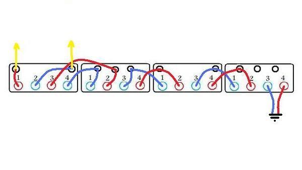
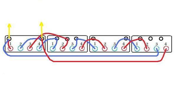
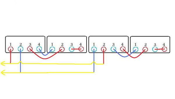
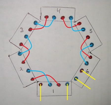
I did some new 'visual aides', the first one below one depicts a stock 4-coil stator with the jumper points included much as they're actually seen (though shown in a straight line, obviously). Each rectangle is a coil/post on the stator, the blue circles/lines trace the path of one winding set, the red the other. The black circles are the jumper points which on the stator are grommets set into the protruding plastic flange at the bottom of each coil and serve as solder connection points. the yellow lines are the output wires to the R/R.
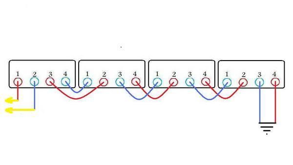
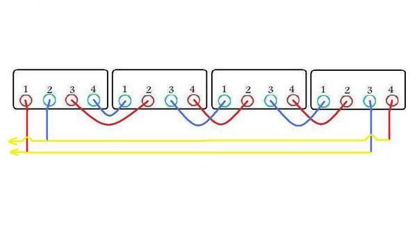
The second picture is the same thing but simplified into more of a a schematic type form and is what I'll likely use to depict future connection schemes. I'll add a couple other types further on for some different perspective, hopefully between them all a coherent pattern will emerge.
I’ve been thinking up some previously untried stator modifications, don’t know how some seemingly obvious ones were missed the first time around, but I guess hindsight is 20/20. Well, not quite, as a few have been failures anyway…
So when I put the stator back to the stock 4-coil configuration, I used four output wires so to be able to try many of the various arrangements with one setup by 'switch-boarding' the wires. The two additional wires are from the two ungrounded ends. In past threads DCT Bob had recommended the ‘four wire mod’ even if there was no immediate plan to use all of them, to allow for future options without having to further access the alt in the motor.
Anyone who took that advice is in luck because there are easy, viable solutions to be had there.
The first one I thought of was a very simple variation of the stock stator. I couldn’t help but wonder why this one never came up early on.
Instead of lifting the grounded ends, then adding an output wire to each and using those along with the two original outputs to go to two separate F/W recs, I just combined the two original outputs and used it and the ungrounded pair to go into one F/W rec, much to the same effect as the ‘3-section with combined outputs’ type mod but with unaltered coil windings. That would cut the working impedance in half again (to a quarter of the ‘standard’ ground lifting scheme) and could also be extrapolated to the six coil config, (resulting in a bit higher working impedance than the ‘3-sec’ mod but likely still within acceptable range)…
This seemed too easy… What was I missing, ‘canceling effect’? Yup… (If two windings on the same core/post are connected so the current flows in opposite directions to each other (resulting in opposite polarity), they cancel each other out.)
It didn’t have any output, I believe due to the polarities of the inner/outer coil windings effectively being backwards on one winding set (I’ve tried unsuccessfully to explain what I mean by that way back in a previous post). If each coil on one winding set were reversed I figured it would work but then ends up being almost the same amount of rework as the ‘3 section’ type mod.
The top one is how I actually connected it and the bottom one is how it would have to be done to work.
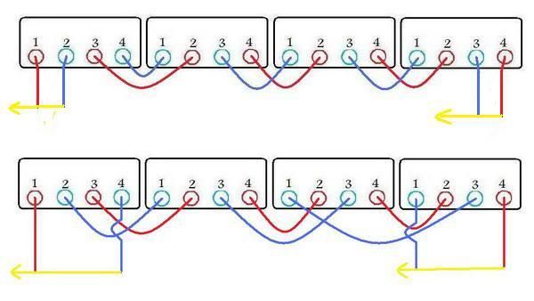
Then a light bulb lit and I thought of a simple way to do it without rearranging the individual coil connections, I swapped/reversed a wire on each winding set one to the other. This worked and produced an acceptable result, 48w at 3450 rpm, on the ‘standard bike emulation setup’.
When I then put it into schematic form, I realized that I had simply reinvented the wheel with Mikes tricky and ingenious ‘E’ scheme that had originally been tested in 6-coil form with good results but was never really pursued when we moved on to other things. (I think that was due to a combination of all the half wave testing and other discussions wanting to be settled with the ‘foam bat’, lol.)
In hindsight I think this was a major opportunity missed as it would have been a big step toward understanding the impedance matching issue, which we hadn’t figured out by that time was the missing link.
Just a note; With my new-found knowledge of 3-phase alt theory, I now also noticed that Mike’s ‘E’ scheme has similarities to the 3-ph delta arrangement but of course with only two windings rather than three. Which makes me wonder again (oh, no!) why the 3 output, 3-section doesn’t work on a 3-ph R/R …? Maybe I had something backwards? (Head pounding on wall).
Testing the alt on the ‘standardized bike emulation’ setup (caps, 55w light, 6w light, 24ohm resistor) with a generic F/W rectifier block at 3450 rpm, I got very consistent results of around 4.6a, 10.7vdc, 48w with both the standard old ‘lifted ground/series’ and mikes ‘E’ scheme. Also similar in output was the dual F/W rectified ‘dual series’ (both winding sets separated and each independently rectified, outputs of recs combined).
(I’m still confused on 'power' vs. voltage. Supposedly it’s all about 'power', so whether a 6v or 12v system it’s the same but seems that ‘break-even’ is achieved at a lower rpm for 6v because it obviously gets there sooner. So does 6v have an advantage in this respect? Or am I missing something fundamental here. Will the higher current demands at 6v drag the voltage down?)
So this round of testing is all pretty much in line with what Bevel bob has been reporting all along with his lifted ground/series 12v system, in that it fully charges the battery at around 3k rpm with a 35w headlight and 4k with a 45w headlight. I’d assume a 55w headlight could indeed be a bit sketchy as it would seem to require 5k rpm or so to ‘break-even’.
The ‘parallel, dual half wave’ that emulates the stock configuration didn’t like the setup at all and put out a pitiful 15w, I don’t know why that low, I would’ve assumed it should be almost double that.
One disclaimer required in all this is that I’ve never tested with a stock R/R and am following the assumption that generic dual h/w rectification is equivalent but with some of the other odd results I’ve been seeing, I can make no guarantees…
The very most interesting/baffling/surprising test was when I put Mike’s ‘E’ on the FH008 Mosfet R/R, 5.26a, 13.47vdc, 70w! Where did that come from?!
I put it back on a different generic rec and back to 48w, I put the ‘lifted ground/series’ on the Mosfet and got 48w. An aberration…, but a good one… More magic wand stuff…
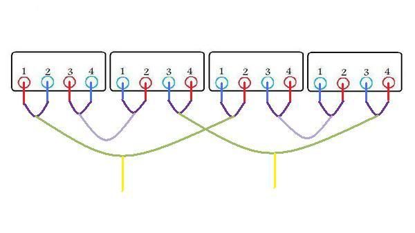
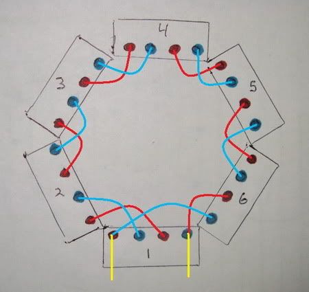
Mikes ‘E’ scheme, depicted in various different pictorial formats, I'll probably continue to use one or more of these to depict other future mod schemes.
This one includes the stock attachment points...
This one is in schematic form...
On this one the grounded ends would need to be separated...
Colors on this one are transposed from the other drawings but it's still functionally the same.
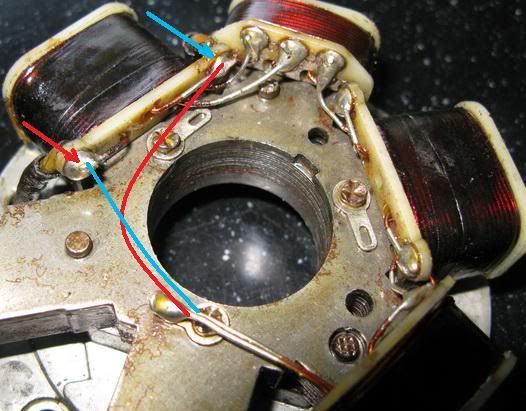
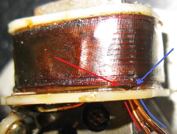
Which wire goes to which winding set needs to be determined for many of the mod schemes. Though both 'end' wires emerge from the same hole on both of my stators, it's easy to visually ascertain which is which. Ringing it out with a meter is the fail-safe way but as can be seen in the photo, they can be differentiated as noted.
Next up was a hybrid between the ‘lifted ground /series’ and 3-section mod, a sort of 2-sec parallel/‘lifted ground /series’.
I disconnected the wires between the 2nd and 3rd coils, connected the 2nd coil pair ends together and also connected the ends on the 4th coil pair. Added an output wire to each of the 3rd coil leads.
Same deal as the ‘E’, 48w on the F/W rec, 71w on the mosfet R/R…!
I’m running out of names for these…
Just for the hell of it, I'll throw this in. There’s another (untested) configuration that’s a confusing one to explain, really begs for some improved standard terminology. The purpose would be to still further reduce the working impedance.
Rather than rewiring the stock inner/outer coils (on each core/pole) to be in series (to act as a single winding as in the ‘Grand series’ and ‘3 section’ mods), what about connecting them in parallel, then alternate in series with the next (coil/core/pole) then parallel to the next? The possibilities go on and on…
The Bottom Line…
While these are all preliminary findings and more thorough testing needs to be done, my obvious conclusion so far is that Mikes ‘E’ scheme in combination with a Shindengen ‘FH’ series R/R gets the nod for it’s simplicity of implementation and reasonable ‘break-even’ point with a 55w light (about 3k rpm, 2k rpm lower than using a standard rec), even with only the 4-coil stator. Another tangible benefit is that the FH R/R's have a stellar reputation for reliability and efficiency.
The Shindengen FH(***)EE series mosfet R/R’s can typically be had on Ebay for $50-65 if you dig a bit, they come in a number of models, 008, 009, 010, 011 and 012 (and an 014 with different connectors). The bikes they came on include (’06 or newer I think) cb600rr’s for the 008, zx10’s-14’s, some gsxr 1000’s, cbr1000rr’s and a couple big cruisers who’s names are escaping me, for the others. The case size is the same on all.
The main difference is I believe that the bigger numbers handle higher current but they’re all overkill for a duc single alt so I don’t see any particular advantage to the higher number models. The one other difference is the FH008EE has a pigtail to the connectors, where the others have the connectors attached directly to the body. So if you want to use your own connector scheme, the 008 has wires to use.
Compatible connectors for all of them can found here;
http://www.easternbeaver.com/Main/Elec_ ... ctors.html
For $125 a new FH0012 with complete connector kit can be found here;
http://lightningcam.com/index.html
If you don’t want to spot the $50-125 for the mosfet and stick with generic rectification or shunt type R/R instead then the choices are pretty open, most any of the mod schemes we’ve covered here (all but the stock alt connection scheme) seem to provide 12v ‘break-even’ somewhere in the low 4k rpm’s with the compromise of a 45w headlight, assuming a battery and/or caps are used. Probably fine for most typical applications. Seems the old ‘lifted ground’ mod may be vindicated after all, as the simplest way to allow for F/W rectification…
Then of course the two extra alt coils ('3-section mod') can be added to get still more power and still lower rpm ‘break-even’, I'll cover that with more detail in a future post.
Hundreds of tests and hundreds of posts, only to come to such simple conclusions, some of which were already out there. Seems as I’ve been chasing my tail and finally caught it. Of course there’s more power to be had and as well, those that need it, so I’ll console myself by rocking back and forth rhythmically, repeating “…but more power is better…more testing needs to be done… but more power is better…more testing needs to be done”…
Just a couple side notes;
On JB Collier’s 6-coil mod; I see no visible way it could be partially wired in parallel so it looks to me like 6 coils in series. With the heavier wire resulting in the same number of turns as the original four coils it should be the same overall wire length, and then the heavier wire should result in lower resistance. I’m sure someone here can roughly calculate what the difference in resistance would be, seems to me it could be as much as 40 percent by going down one gauge size, which may be significant enough so as to be where the advantage to that configuration is…
At one point, around when we were about to start the grand series stuff, Bob mentioned he had a custom rewind scheme up his sleeve that never got implemented and I don’t recall was ever revealed…. What was it…? Bob?
Hopefully to be continued....
Bill
Judging by the lack of any new discussion, looks I’m wasting my time bringing up issues trying to stimulate such. I suppose it's that I’m still inundating everyone with the all at once large posts and everyone is likely a tad burned out on the whole subject too, and maybe this thread has finally just run it’s course and overstayed it’s welcome…
Well in any case, too bad, I can’t chance myself losing interest/momentum in the 11th hour (which I am) so I’m just going to move along with my own plans for winding this down regardless. If I didn’t have so much of it done already, I’d likely abandon it at this point, for the short term at least.
As there are still way too many questions I can’t get answers to for me to be able to sort everything out, I’ll just skip over much of what I wanted to cover, stick to what I more or less know and leave the rest for someone else to deal with someday. Not my loss, nothing there I need for my own project and this post may somewhat anti-climatically resolve the need for more (6 pole) alt power in many of the more typical applications anyway…
As mentioned in my previous post, I’m back to testing, this time starting again from the beginning with the stator put back to the stock 4-coil configuration. The present focus is to find the simplest, most user-friendly mods that anyone who has a small bit of confidence with a soldering iron can accomplish and will yield worthwhile power increases.
In spite of the advantageous discoveries made in the area of impedance matching, incorporating a battery and/or caps into the test setups of late has proved to be a magic wand of sorts that to some degree sidesteps the impedance problem. I was originally using a battery in some of the testing but removed it when in many instances it was skewing the test results as it gained and lost charge, as well as slowing things down while as for each test run I’d have to wait for output readings to stabilize. Eventually I found that a couple paralleled 10k capacitors (a ‘battery eliminator’) provided the beneficial aspects of the battery without the bothersome side effects and I’ve been using them ever since.
Unfortunately a battery and/or caps weren’t incorporated into the majority of testing so we can’t directly compare results with most of the later work and so I needed to do much of it again. This is all DCT Bob’s fault
I did some new 'visual aides', the first one below one depicts a stock 4-coil stator with the jumper points included much as they're actually seen (though shown in a straight line, obviously). Each rectangle is a coil/post on the stator, the blue circles/lines trace the path of one winding set, the red the other. The black circles are the jumper points which on the stator are grommets set into the protruding plastic flange at the bottom of each coil and serve as solder connection points. the yellow lines are the output wires to the R/R.
The second picture is the same thing but simplified into more of a a schematic type form and is what I'll likely use to depict future connection schemes. I'll add a couple other types further on for some different perspective, hopefully between them all a coherent pattern will emerge.
I’ve been thinking up some previously untried stator modifications, don’t know how some seemingly obvious ones were missed the first time around, but I guess hindsight is 20/20. Well, not quite, as a few have been failures anyway…
So when I put the stator back to the stock 4-coil configuration, I used four output wires so to be able to try many of the various arrangements with one setup by 'switch-boarding' the wires. The two additional wires are from the two ungrounded ends. In past threads DCT Bob had recommended the ‘four wire mod’ even if there was no immediate plan to use all of them, to allow for future options without having to further access the alt in the motor.
Anyone who took that advice is in luck because there are easy, viable solutions to be had there.
The first one I thought of was a very simple variation of the stock stator. I couldn’t help but wonder why this one never came up early on.
Instead of lifting the grounded ends, then adding an output wire to each and using those along with the two original outputs to go to two separate F/W recs, I just combined the two original outputs and used it and the ungrounded pair to go into one F/W rec, much to the same effect as the ‘3-section with combined outputs’ type mod but with unaltered coil windings. That would cut the working impedance in half again (to a quarter of the ‘standard’ ground lifting scheme) and could also be extrapolated to the six coil config, (resulting in a bit higher working impedance than the ‘3-sec’ mod but likely still within acceptable range)…
This seemed too easy… What was I missing, ‘canceling effect’? Yup… (If two windings on the same core/post are connected so the current flows in opposite directions to each other (resulting in opposite polarity), they cancel each other out.)
It didn’t have any output, I believe due to the polarities of the inner/outer coil windings effectively being backwards on one winding set (I’ve tried unsuccessfully to explain what I mean by that way back in a previous post). If each coil on one winding set were reversed I figured it would work but then ends up being almost the same amount of rework as the ‘3 section’ type mod.
The top one is how I actually connected it and the bottom one is how it would have to be done to work.
Then a light bulb lit
When I then put it into schematic form, I realized that I had simply reinvented the wheel with Mikes tricky and ingenious ‘E’ scheme that had originally been tested in 6-coil form with good results but was never really pursued when we moved on to other things. (I think that was due to a combination of all the half wave testing and other discussions wanting to be settled with the ‘foam bat’, lol.)
In hindsight I think this was a major opportunity missed as it would have been a big step toward understanding the impedance matching issue, which we hadn’t figured out by that time was the missing link.
Just a note; With my new-found knowledge of 3-phase alt theory, I now also noticed that Mike’s ‘E’ scheme has similarities to the 3-ph delta arrangement but of course with only two windings rather than three. Which makes me wonder again (oh, no!) why the 3 output, 3-section doesn’t work on a 3-ph R/R …? Maybe I had something backwards? (Head pounding on wall).
Testing the alt on the ‘standardized bike emulation’ setup (caps, 55w light, 6w light, 24ohm resistor) with a generic F/W rectifier block at 3450 rpm, I got very consistent results of around 4.6a, 10.7vdc, 48w with both the standard old ‘lifted ground/series’ and mikes ‘E’ scheme. Also similar in output was the dual F/W rectified ‘dual series’ (both winding sets separated and each independently rectified, outputs of recs combined).
(I’m still confused on 'power' vs. voltage. Supposedly it’s all about 'power', so whether a 6v or 12v system it’s the same but seems that ‘break-even’ is achieved at a lower rpm for 6v because it obviously gets there sooner. So does 6v have an advantage in this respect? Or am I missing something fundamental here. Will the higher current demands at 6v drag the voltage down?)
So this round of testing is all pretty much in line with what Bevel bob has been reporting all along with his lifted ground/series 12v system, in that it fully charges the battery at around 3k rpm with a 35w headlight and 4k with a 45w headlight. I’d assume a 55w headlight could indeed be a bit sketchy as it would seem to require 5k rpm or so to ‘break-even’.
The ‘parallel, dual half wave’ that emulates the stock configuration didn’t like the setup at all and put out a pitiful 15w, I don’t know why that low, I would’ve assumed it should be almost double that.
One disclaimer required in all this is that I’ve never tested with a stock R/R and am following the assumption that generic dual h/w rectification is equivalent but with some of the other odd results I’ve been seeing, I can make no guarantees…
The very most interesting/baffling/surprising test was when I put Mike’s ‘E’ on the FH008 Mosfet R/R, 5.26a, 13.47vdc, 70w! Where did that come from?!
I put it back on a different generic rec and back to 48w, I put the ‘lifted ground/series’ on the Mosfet and got 48w. An aberration…, but a good one… More magic wand stuff…
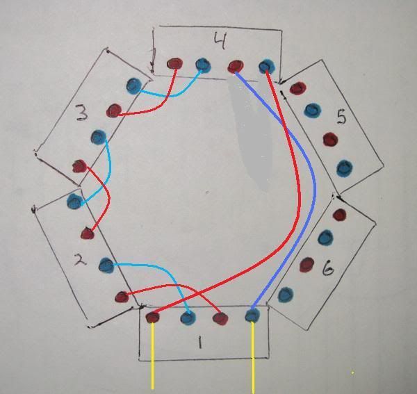
Mikes ‘E’ scheme, depicted in various different pictorial formats, I'll probably continue to use one or more of these to depict other future mod schemes.
This one includes the stock attachment points...
This one is in schematic form...
On this one the grounded ends would need to be separated...
Colors on this one are transposed from the other drawings but it's still functionally the same.
Which wire goes to which winding set needs to be determined for many of the mod schemes. Though both 'end' wires emerge from the same hole on both of my stators, it's easy to visually ascertain which is which. Ringing it out with a meter is the fail-safe way but as can be seen in the photo, they can be differentiated as noted.
Next up was a hybrid between the ‘lifted ground /series’ and 3-section mod, a sort of 2-sec parallel/‘lifted ground /series’.
I disconnected the wires between the 2nd and 3rd coils, connected the 2nd coil pair ends together and also connected the ends on the 4th coil pair. Added an output wire to each of the 3rd coil leads.
Same deal as the ‘E’, 48w on the F/W rec, 71w on the mosfet R/R…!
I’m running out of names for these…
Just for the hell of it, I'll throw this in. There’s another (untested) configuration that’s a confusing one to explain, really begs for some improved standard terminology. The purpose would be to still further reduce the working impedance.
Rather than rewiring the stock inner/outer coils (on each core/pole) to be in series (to act as a single winding as in the ‘Grand series’ and ‘3 section’ mods), what about connecting them in parallel, then alternate in series with the next (coil/core/pole) then parallel to the next? The possibilities go on and on…
The Bottom Line…
While these are all preliminary findings and more thorough testing needs to be done, my obvious conclusion so far is that Mikes ‘E’ scheme in combination with a Shindengen ‘FH’ series R/R gets the nod for it’s simplicity of implementation and reasonable ‘break-even’ point with a 55w light (about 3k rpm, 2k rpm lower than using a standard rec), even with only the 4-coil stator. Another tangible benefit is that the FH R/R's have a stellar reputation for reliability and efficiency.
The Shindengen FH(***)EE series mosfet R/R’s can typically be had on Ebay for $50-65 if you dig a bit, they come in a number of models, 008, 009, 010, 011 and 012 (and an 014 with different connectors). The bikes they came on include (’06 or newer I think) cb600rr’s for the 008, zx10’s-14’s, some gsxr 1000’s, cbr1000rr’s and a couple big cruisers who’s names are escaping me, for the others. The case size is the same on all.
The main difference is I believe that the bigger numbers handle higher current but they’re all overkill for a duc single alt so I don’t see any particular advantage to the higher number models. The one other difference is the FH008EE has a pigtail to the connectors, where the others have the connectors attached directly to the body. So if you want to use your own connector scheme, the 008 has wires to use.
Compatible connectors for all of them can found here;
http://www.easternbeaver.com/Main/Elec_ ... ctors.html
For $125 a new FH0012 with complete connector kit can be found here;
http://lightningcam.com/index.html
If you don’t want to spot the $50-125 for the mosfet and stick with generic rectification or shunt type R/R instead then the choices are pretty open, most any of the mod schemes we’ve covered here (all but the stock alt connection scheme) seem to provide 12v ‘break-even’ somewhere in the low 4k rpm’s with the compromise of a 45w headlight, assuming a battery and/or caps are used. Probably fine for most typical applications. Seems the old ‘lifted ground’ mod may be vindicated after all, as the simplest way to allow for F/W rectification…
Then of course the two extra alt coils ('3-section mod') can be added to get still more power and still lower rpm ‘break-even’, I'll cover that with more detail in a future post.
Hundreds of tests and hundreds of posts, only to come to such simple conclusions, some of which were already out there. Seems as I’ve been chasing my tail and finally caught it. Of course there’s more power to be had and as well, those that need it, so I’ll console myself by rocking back and forth rhythmically, repeating “…but more power is better…more testing needs to be done… but more power is better…more testing needs to be done”…
Just a couple side notes;
On JB Collier’s 6-coil mod; I see no visible way it could be partially wired in parallel so it looks to me like 6 coils in series. With the heavier wire resulting in the same number of turns as the original four coils it should be the same overall wire length, and then the heavier wire should result in lower resistance. I’m sure someone here can roughly calculate what the difference in resistance would be, seems to me it could be as much as 40 percent by going down one gauge size, which may be significant enough so as to be where the advantage to that configuration is…
At one point, around when we were about to start the grand series stuff, Bob mentioned he had a custom rewind scheme up his sleeve that never got implemented and I don’t recall was ever revealed…. What was it…? Bob?
Hopefully to be continued....
Bill
Last edited by wcorey on Tue Oct 18, 2011 5:15 pm, edited 2 times in total.
-
ecurbruce
- Posts: 317
- Joined: Fri Apr 01, 2011 12:43 am
- Location: Hurricane mills TN
Re: n-c alternator modifications: discussion and testing
Bill,
Thanks for finally giving that (Mike's "E") the attention I think it deserves, I've said all along that's the one I'd be using. Until I'm able to run it with my regulator, there was no need for me to bring it up again, but I think you're on the right track with that being one of the simple mods with good results for the novice modifier.
Bruce
-
wcorey
- Posts: 323
- Joined: Sun Jan 31, 2010 1:50 am
- Location: MA USA
Re: n-c alternator modifications: discussion and testing
Believe it or not, the testing continues...
What I’m going to cover here is the installation of two additional coils on the two vacant core/post positions, the basic version that simply stays with the stock coil connection scheme. Still not a real DIY, haven't been ambitious enough to take that on, just downloading more info for those who wish to use it.
The ‘3-section mod’ that has proved to provide the highest output requires a bit more extensive modification and may have more output than is required by some so what's here will be yet another intermediate step in the ‘modification hierarchy’.
Running the 'stock like' 6-coil on the ‘standard bike emulation’ setup with the Shindengen FH mosfet R/R, I got 75w at 2500 rpm, 98w at 6 ohms, 3450rpm (instead of 24 ohms as with the standard setup) and 6k rpm yielded 120w.
Using a generic F/W rectifier reduced most of the mosfet output figures by about 20w but was within about 10w at 6k rpm, so the added efficiency of the mosfet seems to be more apparent at lower rpm’s. An effect of frequency maybe…?
The output of the ‘stock-like’ 6-coil arrangement seems to be held back to some degree (in comparative relation to the 4-coil output) by the impedance matching issue, due to it’s increased wire length (resistance). This is likely why the 6-coil responds well to the ‘3-section mod’ where the 4-coil doesn’t see the same relative benefit from this method. Also possibly why the 6-coil stock w-c alt is rated by Ducati for only 10w over the 4-coil (when it should logically be 30w more)...
To accomplish this mod, two more coils from another stator are obviously needed. The donor coils, once disconnected from each other, slide on/off of the ‘core posts’ after the retaining tabs are bent up straight. There appears to be two different methods by which these tabs are employed. Bruce found the coils on his stators to be retained by separate copper clips that slide in between the post and coil (described here; viewtopic.php?f=3&t=593&hilit=nc+stator+wc+250 ). On the one Bruce's Dad disassembled and both of mine, the last ‘layer’ of sheetmetal the laminated stator core is composed of is simply bent over.
Though only the two output wires from the first coil are required, rather than making the connections of last two coil wires right on the stator I would suggest running them out with the other pair, then the various connection scheme options can be implemented externally to the motor by appropriately combining the wire pairs. Also provides extra insurance in case you get something backwards, lol.
Either of two formats would be practical depending on personal choice. One method is to add the additional two wires to the last pair on the sixth coil, enabling anything from ‘stock-like’, to ‘lifted ground’, to Mikes ‘E’.
The basic two wire version connected as 'E'...
The four wire 'universal' option...
The other (with slightly more complex wiring) is a variation of Dct-Bob’s preferred type setup with a ‘balanced system’ and no requirement for a regulator (the operator becomes the regulator). Pick one of those schemes (‘E’ would be my pick) and do a 4-coil section and a (separate) 2-coil section. Then use the 2 coils that will easily provide low rpm break-even without the headlight and switch in the other 4 (going to a separate rec) when the headlight is on. The outputs of the two rec’s can be combined and with a single or double throw, 4-pole switch they could be actuated simultaneously or be separated for increased optional manual control (2-coil, 4-coil or 2+4 coil).
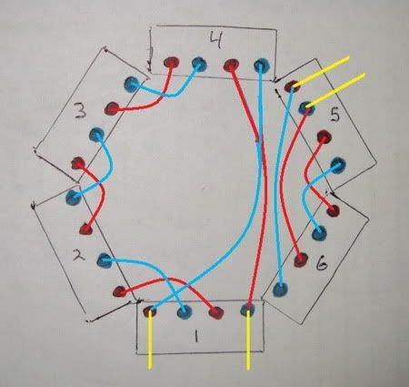
This seems to be becoming a habit, I found something very odd while playing with this configuration. I usually try just about every possible combination of (output wire) connection schemes when I test these multiple output wire setups, even if I’m pretty sure it won’t work, it’s quick, easy and doesn’t hurt anything.
One thing I tried here was running both sections combined into one rec and as expected it put out slightly less power than just the 4-coil section separately. The 4-coil section had a red and white output pair, the 2-coil section had black and green. For this to work at all (to keep the polarities right) red had to be paired with black and white to green.
As I finished reconnecting the 2 coil pair back to it’s own rec (with the alt still spinning) I saw the headlight briefly get brighter. Turns out I had shorted the green wire to the red wire, while both were running on separate recs with the outputs combined. I re-connected the red and green and got increased output power near that of the 4-coil 'E’ with the mosfet R/R, 72w at 3450 rpm (6-coil with generic rec was about 57w). I tried every other similar combination I could think of and none had a similar beneficial result.
On paper it doesn’t make sense to me that it even works at all.
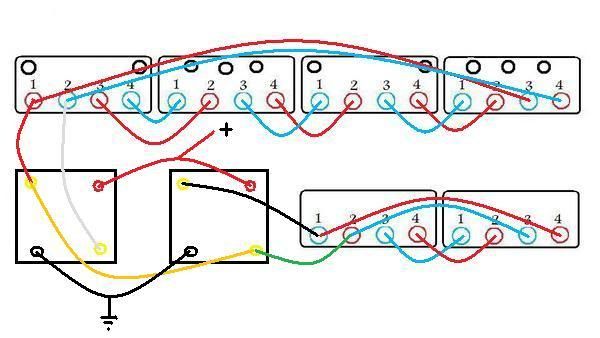
Every time I think I’m starting to understand things a little better something like this happens that reminds me of how relatively clueless I still am with this stuff...
Bill
What I’m going to cover here is the installation of two additional coils on the two vacant core/post positions, the basic version that simply stays with the stock coil connection scheme. Still not a real DIY, haven't been ambitious enough to take that on, just downloading more info for those who wish to use it.
The ‘3-section mod’ that has proved to provide the highest output requires a bit more extensive modification and may have more output than is required by some so what's here will be yet another intermediate step in the ‘modification hierarchy’.
Running the 'stock like' 6-coil on the ‘standard bike emulation’ setup with the Shindengen FH mosfet R/R, I got 75w at 2500 rpm, 98w at 6 ohms, 3450rpm (instead of 24 ohms as with the standard setup) and 6k rpm yielded 120w.
Using a generic F/W rectifier reduced most of the mosfet output figures by about 20w but was within about 10w at 6k rpm, so the added efficiency of the mosfet seems to be more apparent at lower rpm’s. An effect of frequency maybe…?
The output of the ‘stock-like’ 6-coil arrangement seems to be held back to some degree (in comparative relation to the 4-coil output) by the impedance matching issue, due to it’s increased wire length (resistance). This is likely why the 6-coil responds well to the ‘3-section mod’ where the 4-coil doesn’t see the same relative benefit from this method. Also possibly why the 6-coil stock w-c alt is rated by Ducati for only 10w over the 4-coil (when it should logically be 30w more)...
To accomplish this mod, two more coils from another stator are obviously needed. The donor coils, once disconnected from each other, slide on/off of the ‘core posts’ after the retaining tabs are bent up straight. There appears to be two different methods by which these tabs are employed. Bruce found the coils on his stators to be retained by separate copper clips that slide in between the post and coil (described here; viewtopic.php?f=3&t=593&hilit=nc+stator+wc+250 ). On the one Bruce's Dad disassembled and both of mine, the last ‘layer’ of sheetmetal the laminated stator core is composed of is simply bent over.
Though only the two output wires from the first coil are required, rather than making the connections of last two coil wires right on the stator I would suggest running them out with the other pair, then the various connection scheme options can be implemented externally to the motor by appropriately combining the wire pairs. Also provides extra insurance in case you get something backwards, lol.
Either of two formats would be practical depending on personal choice. One method is to add the additional two wires to the last pair on the sixth coil, enabling anything from ‘stock-like’, to ‘lifted ground’, to Mikes ‘E’.
The basic two wire version connected as 'E'...
The four wire 'universal' option...
The other (with slightly more complex wiring) is a variation of Dct-Bob’s preferred type setup with a ‘balanced system’ and no requirement for a regulator (the operator becomes the regulator). Pick one of those schemes (‘E’ would be my pick) and do a 4-coil section and a (separate) 2-coil section. Then use the 2 coils that will easily provide low rpm break-even without the headlight and switch in the other 4 (going to a separate rec) when the headlight is on. The outputs of the two rec’s can be combined and with a single or double throw, 4-pole switch they could be actuated simultaneously or be separated for increased optional manual control (2-coil, 4-coil or 2+4 coil).
This seems to be becoming a habit, I found something very odd while playing with this configuration. I usually try just about every possible combination of (output wire) connection schemes when I test these multiple output wire setups, even if I’m pretty sure it won’t work, it’s quick, easy and doesn’t hurt anything.
One thing I tried here was running both sections combined into one rec and as expected it put out slightly less power than just the 4-coil section separately. The 4-coil section had a red and white output pair, the 2-coil section had black and green. For this to work at all (to keep the polarities right) red had to be paired with black and white to green.
As I finished reconnecting the 2 coil pair back to it’s own rec (with the alt still spinning) I saw the headlight briefly get brighter. Turns out I had shorted the green wire to the red wire, while both were running on separate recs with the outputs combined. I re-connected the red and green and got increased output power near that of the 4-coil 'E’ with the mosfet R/R, 72w at 3450 rpm (6-coil with generic rec was about 57w). I tried every other similar combination I could think of and none had a similar beneficial result.
On paper it doesn’t make sense to me that it even works at all.
Every time I think I’m starting to understand things a little better something like this happens that reminds me of how relatively clueless I still am with this stuff...
Bill
Return to “Ducati Singles Main Discussions (& How to Join)”
Who is online
Users browsing this forum: No registered users and 59 guests