n-c alternator modifications: discussion and testing

Ducati single cylinder motorcycle questions and discussions, all models. Ducati single cylinder motorcycle-related content only! Email subscription available.
Moderator: Morpheus

Moderator: ajleone

MotoMike
Posts: 487
Joined: Wed Aug 04, 2010 3:40 am

Delta

Postby MotoMike » Tue Jul 19, 2011 10:05 pm

DewCatTea-Bob wrote:[
____ Well now I see that not only can't it work for single-phase (with OUR three-sections), it's also a very questionable circuit even for true '3-phase' !!! - As it would still encounter the very same issue although at a much reduced amount,
____


The Delta is a difficult system to get your mind around I will give you that. I don't think I have divined all it's secrets, but have just analyzed it enough to say it works well for high current applications in a three-phase circuit. Delta is fairly commonly used in industry for it's ability to produce more current than an equivalently sized y winding scheme. No diodes are needed to make it work as a three phase source. If you want to try to flow current through it here is a schematic, I think I can talk you through it. If anyone wants to do it themselves, I recommend marking the polarity on the coils every 60 degrees starting at zero. In this way you will always catch one coil as its induced voltage is zero, and in this way not have to consider it when trying to flow current.


Image
Mike

ecurbruce
Posts: 313
Joined: Fri Apr 01, 2011 12:43 am
Location: Hurricane mills TN

Re: 6volt or 12 volt?

Postby ecurbruce » Thu Jul 21, 2011 11:31 am

Bill says--" Still scheming and plotting on converting the 'three section stator' to three phase... "

So, I gather you're not finished then?


And--" I thought of a potential solution, an 8 magnet rotor and re wiring of the stator so the two coils of each pair are 180 degrees
opposite each other (instead of 60 degrees apart/next to each other) and the wiring/polarity on one is reversed (since they're wound in opposite directions and unlike the 'normal' configuration, would hit
the same polarity magnet at the same time)."

Do you have the 8 magnet rotor? If so, do you know it's origional application, and the stator that came with it , how is it wired, and was it single phase or three phase?

And-- "What I can't seem to reconcile is if there's a difference between a coil that's wound in a given direction and one that's connected up in a given (pos/neg) direction (to obtain a given polarity). My understanding is that if a coil is wound in one direction, when power is applied or produced, it has a particular polarity that would reverse if either it was wound in the opposite direction or if the power connections were reversed (or also if the magnet were reversed). It seems that it's one polarity or the other no matter the method of getting there and the end result would be effectively the same... Yes?"

I see that the same as you do, Bill, and I see that with a six magnet rotor the end result of reversing the polarity of three of the oposing coils would end up with the same end result as you had before reversing them. What I don't know is what affect the 8 magnet rotor would have, and if you'd like to wire it and run it, I'd sure like to see the results!

Just to be clear, you're talking about paring up Aa with Dd, Bb with Ee, Cc with Ff, right? And reversing polarity on Dd, Ee, and Ff?

Bruce.

wcorey
Posts: 323
Joined: Sun Jan 31, 2010 1:50 am
Location: MA USA

Re: 6volt or 12 volt?

Postby wcorey » Thu Jul 21, 2011 7:58 pm

So, I gather you're not finished then?


Hah, 'finished' is a relative term. Finished with most aspects I guess but it seems the possibilities go on and on.


Do you have the 8 magnet rotor?


No, or I would have already tried it and wouldn't be asking these questions. I can either make one from scratch or more likely modify one of the ones I already have, I've figured out a few different viable options there. I had already dissected one of the adapted Denso rotors and removed it's magnets, would be just a matter of reducing their number from 12 to 8 and spacing them evenly, which I've already worked out a couple ways of doing. Either way a bit of a project that I may never get around to doing.


Just to be clear, you're talking about paring up Aa with Dd, Bb with Ee, Cc with Ff, right? And reversing polarity on Dd, Ee, and Ff?


Yes on the pairings, no on the reversals, those would be either of Aa, Cc and Ee, or Bb, Dd and Ff.


I see that the same as you do, Bill, and I see that with a six magnet rotor the end result of reversing the polarity of three of the oposing coils would end up with the same end result as you had before reversing them. What I don't know is what affect the 8 magnet rotor would have, and if you'd like to wire it and run it, I'd sure like to see the results!


Yes, with a six magnet rotor nothing would effectively change.

The effect of the 8 magnet rotor should be 3ph output. Given that 3ph is supposed to be more efficient, I'm not sure if that would mean higher wattage output or less effort (hp) required to get what we already have and maybe more power at lower rpm.
A simple way to look at the 8 magnet setup is to draw 8 points in a circle to represent the rotor magnets. To represent the stator, start by drawing two points inside the 8 point circle that line up to the 12 o'clock and 6 o'clock magnet positions. You'll see that when you then add the other 4 equidistant stator points, one of the other 180 degree pairs will be just past a set of n/s magnets and the third pair will be just approaching a set, so each of the three coil pairs are always a third of a phase (120 degrees) separated in relation the the magnet pairs. The issue on the stator is that all the coils must be the same polarity, which I think can be accomplished by simply reversing the connections on every other one, so say's my compass anyway...


On another note, I have 5 various 3ph alts that I had adapted for use on the 450 a while back. 4 of the 5 (all 18 coil, 12 magnet) are obviously wired as a 'star' configuration with 3 single output wires (one from each coil set) and the other three wires bundled together and terminated/isolated with no outside connection. One stator however (the most 'modern', highest wattage one, 2009 ZX14, 15 coils, 20 magnets), looks to be a delta configuration, wired similarly to the others but the 3 output wires are pairs. It's pretty difficult to physically trace the wires and I haven't actually separated the outputs to ring them out but the only way that can work is with delta.

As that alt is such ridiculous overkill at 350 watts (and therefore useless to me in it's present form), I'm very tempted to remove 9 of the 15 coils (cores and all) to down-rate the output (to a 100+ watts) and see how it then behaves. It has a very robust looking stator with much heavier coil wires than any of the others and a beautifully machined rotor that weighs about the same as the stock Ducati aluminum one, seems like a shame to waste it at this point.
Would possibly provide a useable baseline comparison to the single phase setups and I can even try it in 'star' vs 'delta'...

Bill

ecurbruce
Posts: 313
Joined: Fri Apr 01, 2011 12:43 am
Location: Hurricane mills TN

Re: 6volt or 12 volt?

Postby ecurbruce » Thu Jul 21, 2011 9:48 pm

Bill says"--Yes on the pairings, no on the reversals, those would be either of Aa, Cc and Ee, or Bb, Dd and Ff.

Yes, after more study on this today, I see reversing Dd,Ee,Ff creates a phasing imbalance, ending up with more of one polarity than the other...oops.

I plotted out the sine wave of the 8 magnet rotor on the six coil stator, and yes it makes the three phase waves, but only equivelent to one pair of coils output. There's only output from two coils at any peak moment in time, where the six coil- six magnet configuration has output from six coils ( in single phase) at any peak moment. I know the three phase is more efficient, but I don't know if it's enough to make up the difference,

Bruce.

wcorey
Posts: 323
Joined: Sun Jan 31, 2010 1:50 am
Location: MA USA

Re: 6volt or 12 volt?

Postby wcorey » Fri Jul 22, 2011 1:18 am

I plotted out the sine wave of the 8 magnet rotor on the six coil stator, and yes it makes the three phase waves, but only equivelent to one pair of coils output. There's only output from two coils at any peak moment in time, where the six coil- six magnet configuration has output from six coils ( in single phase) at any peak moment.


Plotting sine waves is getting a little out of my realm, but it seems to me something is missing here, that being time.
What either one does in one 'peak moment' is only relevant here if that moment has a length of time attached to it and is compared to the other alt in a moment of the same duration. What you describe, with the absence of duration, seems to me as simply the difference between how any single phase and any three phase alt works. Like a 'big bang' parallel twin motor that fires both pistons on the same stroke as opposed to one that's timed to fire each on alternating strokes, same amount of power per rpm (time) but produced in a different way.
When the peak occurs on the 1ph 6 pole alt, producing six simultaneous outputs , there is a space of time before the next peak. In that same time frame the 3ph 8 pole alt makes 8 outputs (?), spread out over 4 separately occurring events but still within the same unit of time, therefore producing more output simply by virtue of having the two additional magnets moving over the 6 coils. Then factor in the increased 3ph efficiency.
My details may be off but I'm pretty sure my concept is sound. I think :? ...

Bill
Last edited by wcorey on Fri Jul 22, 2011 1:00 pm, edited 1 time in total.

ecurbruce
Posts: 313
Joined: Fri Apr 01, 2011 12:43 am
Location: Hurricane mills TN

Re: 6volt or 12 volt?

Postby ecurbruce » Fri Jul 22, 2011 10:48 am

Bill,

You may be right... you may have to build it to find out,,, :)

wcorey
Posts: 323
Joined: Sun Jan 31, 2010 1:50 am
Location: MA USA

Re: 6volt or 12 volt?

Postby wcorey » Sun Jul 24, 2011 7:53 pm

Curiosity got the best of me and I went ahead and put together an 8 pole rotor out of the modded 12 pole one I had dissected, a bit mickey mouse but fine for testing. If I were to use it in my 450 motor I think completely potting the magnets in flush with epoxy would be a pretty permanent and useable solution.

Image

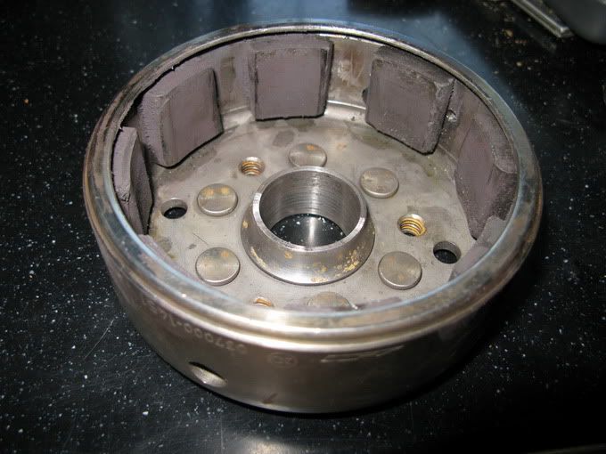
The stator was a pretty easy rewire from the three section setup, I left the 6 external connections so it's possible to switch from 'star' to 'delta' configurations. Unfortunately the single phase three section config doesn't work with the 8 pole so really direct apples/apples comparison isn't possible as the number and type of magnets are different from the 6 pole. I'm guessing that if I had wider magnets on the 8 pole rotor that
I'd get more power...

The results are...

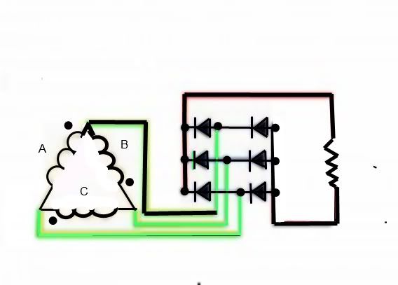
Modded '3 section' 6 coil n/c stator, (3) coil sets (pairs) 180 degrees separated, 3ph, with 8 magnet rotor into Shindengen FH008ee mosfet reg/rec. For 'star' config the three small coil wires are connected/combined and isolated, the three large coil wires go the the R/R inputs. For 'delta' config each small coil wire connects to the first coil of the next set (the large coil next to it), and the resulting three pairs of wires go to the three R/R inputs.
(just to clarify, each coil set consists of one large coil and one small, so each pair has one wire connecting the two coils and one coming out of each)

FH008 pos output through current meter to capacitors, neg output straight to caps, vdc taken at caps, 55w (or maybe 60w) light to caps pos/neg. (Where noted as an addition to the light, coil and various value resistors connected to caps same as light).

Caps + light
star----4310rpm---4.28a---14.18vdc---60.69w
delta--4310rpm---4.248a---14.21vdc---60.81w

Caps + light + 5 ohm coil
star----4310rpm---6.95a---13.81vdc---95.97w
delta--4310rpm---6.94a---13.83vdc---95.98w

Caps + light + 5 ohm coil + 5 ohm res
star---4310rpm---7.62a---10.28vdc---78.33w
delta--4310rpm---9.40a---13.47vdc---126.61w

Caps + light + 5 ohm coil + 4 ohm res
delta--4310rpm---10.17a---13.77vdc---140.03w

Caps + light + 5 ohm coil + 3 ohm res
delta--4310rpm---10.61a---12.69vdc---134.64w

The stator only went about 5 degrees above ambient throughout the testing, if I recall correctly that's about 10 degrees less than the single ph was getting up to. I get the impression from to sound of the drive motor that it also requires less power to spin it under load but haven't done any actual comparison testing there. With the single ph setup I could hear the difference in pitch at higher/lower loads but with the three ph couldn't discern any difference.
The two configurations start off virtually the same but as the load increases delta has a distinct advantage, as it's supposed to. Could be due to it's theoretical lower working impedance. The star should have a voltage advantage at lower rpm that isn't evidenced at 4310 or 3450 rpm, I'd like to try it at a much lower rev to see but not sure I want to take the time to set that up...


For comparison I added these single phase results from the post on page 37.

3 sections with outputs combined, then into Shindengen FH008ee mosfet reg/rec (using only two of the three inputs
FH008 pos output through current meter to capacitors, neg output straight to caps, vdc taken at caps, 55w (or maybe 60w) light to caps pos/neg. (Where noted as an addition to the light, coil and 3ohm res connected to caps same as light).

Caps + light
4310rpm---4.24a---14.16vdc---60.73w

Caps + light + 5 ohm coil + 5 ohm res
4310rpm---6.69a---13.98vdc---93.52w

Caps + light + 5 ohm coil + 3 ohm res
4310rpm---9.95a---11.96vdc---119w


My overall conclusion is that the three phase (delta) conversion is a noticeable improvement in high load output (that's likely not required for most of our applications anyway) and some anecdotal observations give it an edge in efficiency but it's obviously not a not a big enough advantage for most people to go through the bother of constructing a rotor to implement it.

Bill
Last edited by wcorey on Wed Oct 05, 2011 3:02 am, edited 2 times in total.

ecurbruce
Posts: 313
Joined: Fri Apr 01, 2011 12:43 am
Location: Hurricane mills TN

Re: 6volt or 12 volt?

Postby ecurbruce » Mon Jul 25, 2011 12:10 am

Nice work Bill, isn't fabricating fun?

I've a question, does both of your test electric motors have the same size shaft?
Also, do any of your multimeters measure hertz?

wcorey
Posts: 323
Joined: Sun Jan 31, 2010 1:50 am
Location: MA USA

Re: 6volt or 12 volt?

Postby wcorey » Mon Jul 25, 2011 12:21 am

Sometimes, yes and yes.

Bill

MotoMike
Posts: 487
Joined: Wed Aug 04, 2010 3:40 am

Re: 6volt or 12 volt?

Postby MotoMike » Mon Jul 25, 2011 4:00 am

Bill

You are definatly the man. Never let it be said it can't be done. I had my doubts you'd get the magnets aligned right, but you must have. I'm wondering how close the magnest are to the core compared to the originals. I think your numbers are impressive as there is no way those magnets are as effectively coupling the field through the cores as the original does with it's laminate bridge between the magnets getting very close to the cores.

I think you are right that the delta does a better job in higher current applications. at least that is what I recall from training many years ago.

Now with most of the dust settled on this, I think I'd be inclined to make the single phase mode with the three sets of paralell coils through a single phase RR. You get good numbers from that combo.

Thanks much for all the hard work.

Mike


Return to “Ducati Singles Main Discussions (& How to Join)”

Who is online

Users browsing this forum: No registered users and 34 guests