Bill, and Bob,
I hesitate to get into this, because you guys are on a roll and making headway for the most part, but I'll just say
as far as a modern 3 phase alternator goes, the last one that I took apart was one from a volkswagon, which robbed the diodes from, and I noticed that the diodes are placed just at the ends of the coil windings, at each end of the windings, before anything else happens with the windings, so as to isolate them from anything else going on with the circuit. This may be a missing piece in the schematic that you guys are using and looking at. I know that our project is not all as a modern regulator is, but maybe this piece of the technology would be useful at this point?
Bruce.
n-c alternator modifications: discussion and testing
Moderator: ajleone
-
ecurbruce
- Posts: 317
- Joined: Fri Apr 01, 2011 12:43 am
- Location: Hurricane mills TN
-
wcorey
- Posts: 323
- Joined: Sun Jan 31, 2010 1:50 am
- Location: MA USA
Re: 6volt or 12 volt?
Bob, I know most people would ignore/avoid such an onerous task but I also know you're not one of them. Thanks for taking the time to respond. I still disagree on the characteristics of the star/delta being so much alike, everything I'm reading says they each have their specific and potentially significant particular advantages...
Bruce, I have a small pile of 3ph bike alternators and none have any additional components other than the windings. The majority of schematics I can find use the typical 6 diode arrangement for the rec, the Shindengen mosfet ones I have replace the three 'negative side' diodes with mosfet's but is otherwise also the same.
On another note, the four wire star (wye) type stator configuration doesn't require the center tap to work and can be rectified the same way as the delta type. Apparently the center wire is a neutral and only carries current if there's an imbalance between the three winding sets, so just because a stator has only three outputs doesn't mean it has to be a delta configuration.
Looks like the difference in resistance between the two configurations is because with delta, any two wires go through only one winding set but with star, across any two (other than the neutral) wires goes through two winding sets in series.
I realized that just as Bob's latest 3ph reg/rec test emulated a delta configuration on the three section stator, the previous similar test I had done emulated a star configuration in a similar way. My mistake there was in connecting the 'center tap' wires to the negative output on the reg/rec so I tried it with those three left tied together but unconnected to anything else. Still a disappointing result but an improvement none the less, at 4300 rpm, 10.3vdc with just the caps, but only about 3.3vdc and .35a with a 5ohm load, about 1w.
I'd still love to find a rotor with the appropriate diameter and number of magnets to try and configure a six coil Ducati stator as three phase...
Bill
-
DewCatTea-Bob
- Posts: 2897
- Joined: Sun Nov 01, 2009 10:53 am
- Location: Near SE side of Lake Michigan
The Y-star type is the only type that's really different !
" Thanks for taking the time to respond. "
____ I was going to put it off until I had a more extended time to completely tackle it but, then thought I may never get to it at all, so started it but hadn't finished, (as could be noted since I hadn't signed-off on the post). _ It's finished now though.
" I still disagree on the characteristics of the star/delta being so much alike, everything I'm reading says they each have their specific and potentially significant particular advantages... "
____ So what's to "disagree" with ? _ Certainly nothing I meant to say !
The main-difference between Types "A", "B" & "C" is basically only the method-style of THE connections.
The only type which really stands-out, is the Y-star type ! _ As I've agreed that IT would certainly have altered characteristics, since IT obviously doesn't make any use of any 'common' type wire-leads ! _ Thus making it particularly different from it's (otherwise confusable) look-a-like "B" type, (which due to the one/main difference of having a 'common' or not, makes a significant alteration of output-characteristics !).
" the four wire star (wye) type stator configuration doesn't require the center tap to work and can be rectified the same way as the delta type. "
____ Possibly so but, the "neutral" is really merely a 'common' and not at all a true 'center-tap', since each of the separate (off phase) stator-windings are whole & uninterrupted and separated (except at the end-connections).
" Apparently the center wire is a neutral and only carries current if there's an imbalance between the three winding sets, "
____ That doesn't make sense to MY understanding.
" Looks like the difference in resistance between the two configurations is because with delta, any two wires go through only one winding set but with star, across any two (other than the neutral) wires goes through two winding sets in series. "
____ I believe that you see that correctly but, the Y-star type is not the same as the similar-appearing "B" type -(with it's added 'common') !
They're obviously two different animals !
Whereas types "A", "B" & "C" are actually all the very-same, (EXCEPT for their connection-method/types !), electrically (although perhaps not physically).
" I realized that just as Bob's latest 3ph reg/rec test emulated a delta configuration on the three section stator, the previous similar test I had done emulated a star configuration in a similar way. My mistake there was in connecting the 'center tap' wires to the negative output on the reg/rec so I tried it with those three left tied together but unconnected to anything else. Still a disappointing result but an improvement none the less, at 4300 rpm, 10.3vdc with just the caps, but only about 3.3vdc and .35a with a 5ohm load, about 1w. "
____ I'm having difficulty realizing what all you're meaning for sure, on all this... It's too bad you can't show your very-own diagrams to indicate the connection-schemes which you tried-out !
If you take an existing pic.diagram (loaded within your PC) and right-click it, you can then choose the 'edit' feature to alter the pic.gram pretty-much as need be.
" I'd still love to find a rotor with the appropriate diameter and number of magnets to try and configure a six coil Ducati stator as three phase... "
____ I don't think that could be done,, besides, with a battery in the system, three power-phases wouldn't make any real difference !
Finished-Cheers,
-Bob
You do not have the required permissions to view the files attached to this post.
PLEASE NOTE... If this-post is not-yet signed-off with '-Bob', then I'm still in the process of completing it,, and if not also included with 'DCT' near bottom as well, then I may edit this post's wording at a later time. - Dct.Bob
-
wcorey
- Posts: 323
- Joined: Sun Jan 31, 2010 1:50 am
- Location: MA USA
Re: 6volt or 12 volt?
Sorry to any/all who are still following this...
Not usually my thing but I'm in a bit of a confrontational mood, so at risk of further diluting our thread with a useless (to this thread) back and forth as you (Bob) did earlier on with MotoMike (and consequently chasing away a valuable contributor to this thread with petty personal attacks, just because you have a really thick skin for it doesn't mean everyone else want's to go there. That would have gotten you a warning and/or vacation on any civilized forum. If you weren't a moderator... ).
Now that I've set the tone here,
 ...
...
I guess I missed that somehow, or maybe I read your post before that was added? That's a bad habit of yours in my opinion, leaving half concocted posts to be half read by all. It's a pain in the neck going back and re reading all your posts for new content, you should complete them first, like everyone else does in every forum I've ever been on...
This is what you wrote that I'm referring to, seems very obvious what you meant to say but as usual I could be reading it wrong;
which was in response to what I wrote;
Could you point me in the direction (a link or publication) of where you get this understanding, as I'd like to read something with an alternative view but can't seem to find anything that questions the conventional wisdom that is out there in mass quantities. I can certainly provide many links to where my info comes from.
This is a pretty short one to read; http://www.itacanet.org/eng/elec/edu/pt14.pdf see the text just below figure 14.5 for a specific example of my quote.
'A' has no connections... Just to be clear, I haven't been comparing anything 3ph to the 'A' "type" because it's not really a 'type' at all and doesn't exist in practical terms. It's just a 'fill in the blanks' depiction that could represent anything you want by connecting it in different ways, as you have since indicated. In all the reading I've done, this is the only place I've seen it. Everything I have seen refers to only two types of 3ph, delta or (star, 'wye', 'y') and unless the dozen or more articles I've now read are all collectively wrong, there are significant 'electrical' differences between the two beside the connection scheme. The neutral in the star type is optional, whether it's there or not doesn't change it to a different type or alter any of it's major characteristics.
I think you need to do some reading up on this, though I guess you won't believe the 'professionals' anyway as they've obviously been tainted by their years of conventional education and don't see the 'big picture' or whatever...
How so, exactly?
Again, I can't find anything online to support that, there are only two types...
I took the 'first' wire in each (of the three) section and connected each to it's own 3 ph reg/rec input, then took the 'second' (or other) wire from each section and combined them but left them unconnected to anything else. Just as you told me it should have been obvious to me that your delta wiring scheme applied to the three sec alt because it was indeed so obvious, I'm saying the same back to you (relative to the 'three section star configuration') in this instance.
As already stated, I thought it would be so obvious that I needn't have bothered...
You'll probably disagree but 3ph is supposed to be 150% more efficient in producing power within what power/rpm is being used to spin it, compared to single phase.
I'm done for now, maybe this post is finished/complete, maybe it's not...
Bill
Not usually my thing but I'm in a bit of a confrontational mood, so at risk of further diluting our thread with a useless (to this thread) back and forth as you (Bob) did earlier on with MotoMike (and consequently chasing away a valuable contributor to this thread with petty personal attacks, just because you have a really thick skin for it doesn't mean everyone else want's to go there. That would have gotten you a warning and/or vacation on any civilized forum. If you weren't a moderator... ).
Now that I've set the tone here,
____ Your saying that leads me to think that you didn't bother to read and/or make-note of the footnotes which I had added to the bottom-side of my posted-pictures. _
I guess I missed that somehow, or maybe I read your post before that was added? That's a bad habit of yours in my opinion, leaving half concocted posts to be half read by all. It's a pain in the neck going back and re reading all your posts for new content, you should complete them first, like everyone else does in every forum I've ever been on...
____ So what's to "disagree" with ? _ Certainly nothing I meant to say !
This is what you wrote that I'm referring to, seems very obvious what you meant to say but as usual I could be reading it wrong;
____ Seems you've dug-up some related info,
however I'm somewhat doubtful of those stated differences.
which was in response to what I wrote;
" I still disagree on the characteristics of the star/delta being so much alike, everything I'm reading says they each have their specific and potentially significant particular advantages... "
" Apparently the center wire is a neutral and only carries current if there's an imbalance between the three winding sets, "
____ That doesn't make sense to MY understanding.
Could you point me in the direction (a link or publication) of where you get this understanding, as I'd like to read something with an alternative view but can't seem to find anything that questions the conventional wisdom that is out there in mass quantities. I can certainly provide many links to where my info comes from.
This is a pretty short one to read; http://www.itacanet.org/eng/elec/edu/pt14.pdf see the text just below figure 14.5 for a specific example of my quote.
The main-difference between Types "A", "B" & "C" is basically only the method-style of THE connections...
...Whereas types "A", "B" & "C" are actually all the very-same, (EXCEPT for their connection-method/types !), electrically (although perhaps not physically).
'A' has no connections... Just to be clear, I haven't been comparing anything 3ph to the 'A' "type" because it's not really a 'type' at all and doesn't exist in practical terms. It's just a 'fill in the blanks' depiction that could represent anything you want by connecting it in different ways, as you have since indicated. In all the reading I've done, this is the only place I've seen it. Everything I have seen refers to only two types of 3ph, delta or (star, 'wye', 'y') and unless the dozen or more articles I've now read are all collectively wrong, there are significant 'electrical' differences between the two beside the connection scheme. The neutral in the star type is optional, whether it's there or not doesn't change it to a different type or alter any of it's major characteristics.
I think you need to do some reading up on this, though I guess you won't believe the 'professionals' anyway as they've obviously been tainted by their years of conventional education and don't see the 'big picture' or whatever...
...the Y-star type is not the same as the similar-appearing "B" type -(with it's added 'common') !
They're obviously two different animals !
How so, exactly?
Again, I can't find anything online to support that, there are only two types...
" I realized that just as Bob's latest 3ph reg/rec test emulated a delta configuration on the three section stator, the previous similar test I had done emulated a star configuration in a similar way.
____ I'm having difficulty realizing what all you're meaning for sure, on all this...
I took the 'first' wire in each (of the three) section and connected each to it's own 3 ph reg/rec input, then took the 'second' (or other) wire from each section and combined them but left them unconnected to anything else. Just as you told me it should have been obvious to me that your delta wiring scheme applied to the three sec alt because it was indeed so obvious, I'm saying the same back to you (relative to the 'three section star configuration') in this instance.
It's too bad you can't show your very-own diagrams to indicate the connection-schemes which you tried-out !
As already stated, I thought it would be so obvious that I needn't have bothered...
" I'd still love to find a rotor with the appropriate diameter and number of magnets to try and configure a six coil Ducati stator as three phase... "
____ I don't think that could be done,, besides, with a battery in the system, three power-phases wouldn't make any real difference !
You'll probably disagree but 3ph is supposed to be 150% more efficient in producing power within what power/rpm is being used to spin it, compared to single phase.
I'm done for now, maybe this post is finished/complete, maybe it's not...
Bill
-
DewCatTea-Bob
- Posts: 2897
- Joined: Sun Nov 01, 2009 10:53 am
- Location: Near SE side of Lake Michigan
Further Confusion concerning Alt.stator Connection-types...
____ FIRST-OFF,, to anyone who's really bothered that I start many of my extended posts (in a timely, more orderly fashion) but don't also get completely-finished all at once,
I'm sorry about that but, if I don't get started on a post, then chances are fairly great that I'll NEVER get-around to posting any response-post at all ! _ (Such actually happens fairly regularly.)
So for those who are indeed bothered that my extended postings are not totally completed when first partially-posted, I've (long) left them a hintful-clue that my post is not finished if I haven't signed-off on it (with my name near the bottom of what I've posted). _ So, if ya just wish to read my postings only after they're all-done, then simply skip-by any post of mine that's not so-indicated as finished.
" so at risk of further diluting our thread with a useless (to this thread) back and forth as you (Bob) did earlier on with MotoMike "
____ I don't agree that the back & forth head-bunting with Mike was useless. _ It brought-up an opportunity to detail-out some mainstream-misconception, and allows the reader to see termed-points narrowed-down, for a sharpened understanding of things.
" (and consequently chasing away a valuable contributor to this thread with petty personal attacks, "
____ Not only is this thinking a strike from out of the blue-yonder, but also I find it
absurdly preposterous !
As I don't EVER engage in any kind of personal-attacks ! _ Such notions are purely conceived-of within the negatively-inclined mind of the individual-reader.
__ I challenge anyone to point-out any wording I've ever used that's meant as any kind of a 'put-down' of ANY individual !
(As such does not exist since I'm not the type who's so inclined to promote such purposeful ridicule !)
__ And I don't think I've chased Mike away, as he's previously established a pattern of high participation/vacation/participation, so I assume he's been in his off-mode lately.
(Mike, how about a little more input ?)
" That would have gotten you a warning and/or vacation on any civilized forum. If you weren't a moderator... ). "
____ Furthermore unfounded !! - I've done nothing of the sort to even come close ! _ So you'd be wasting your time to try to prove so !
__ That I've been a 'moderator' is irrelevant. _ As far as such is concerned, I consider myself no different from you or Mike or any other reg.member here (other than Jim) !
____ That's doubtful, as I most always add my footnote-wording along at the same time when I'm presented with the caption-box created for the entered-pic. _ However I sometimes attempt to upload the pic first, just to make sure it will get posted first,, and doing that may leave a temporary window (up to 5-minutes long), before the footnote then gets added & posted right-afterword.
So I believe it's more likely that you clicked-on the pic (to enlarge it) and thus lost sight of the captioned-footnote.
" That's a bad habit of yours in my opinion, leaving half concocted posts to be half read by all. It's a pain in the neck going back and re reading all your posts for new content, you should complete them first, "
____ I wish I could do that but, then if I got any posts posted, they would then be no longer than a couple of short paragraphs (and be only about as coherent as most posts posted by the average poster).
I realize that a very few times I have indeed put-up poorly concocted partially started postings, (which only occurs due to more important interruptions at my end, at the time), but if ya note that DewCatTea-Bob is still logged-in, then it's no doubt just a very temporary state, and a simple refreshing of the page could review the interrupted post, as no longer merely "concocted".
Otherwise my posts are completed when first posted, except for being 'edited' for improved coherency, which I very often do later.
If I had to put-off posting until I obtained the time to fully complete an extended post, it would then not get done within a timely-manor (if ever). _ And if I don't go-ahead & post that which I've got-done thus-far (whenever interrupted), I then take the risk of loss, (which I really HATE to no-end !). _ And whenever such loss of thus-completed text has occurred, I dread & refuse to do it over again, (and such has happened more times than I care to recount !).
Also, I'm a disabled old-fogey who not only never learned to type but also have only ONE finger with which to poke keys ! _ So I can't possibly put into words my thoughts as fast as I think of them, and by the time I get one thought typed-out, the others are forgotten until I later read my own post and then get reminded of what I had forgotten to include. _ So rather than leave it as is, I then add-in the missing thoughts.
Before, I (possibly wrongly) assumed that what you were then referring to was differences between the "B" type (with only one common-lead), and the others (which seem no different 'electrically', other than the obviously different connection-arrangements).
But at that time, I didn't realize that you could've been actually meaning to refer to a Y-star type, (which truly is different !), and I clearly understand and had since agreed that IT indeed would have a separate set of characteristics from all the others !
__ But anyhow, you should now understand that I actually had never disagreed about any claimed differences concerning the (plain!) 'Y-star' type, (since at that time, IT was not an established 'type' for consideration.
____ Other that that which I'm telling you, I know of no other...
My "understanding" comes from my very-own deductive-abilities, (such as being able to see 3-dimensionally within my mind's-eye, [just as many males normally do]).
__ Of course you too also ought to be able to envision that the common-lead (of type-B) is no different electrically, than the set-of-three common-leads of the Delta-type. - (Kind-of sort-of like a single [isolated] 'ground' type mass -[in the form of wire], [although not the actual 'Ground' of course ! - Merely just A "common".].)
__ Do I need to draw another picture for you ?
" as I'd like to read something with an alternative view but can't seem to find anything that questions the conventional wisdom that is out there in mass quantities. "
____ The "what's what" which seems going-on, is that you seemingly thus-far haven't been putting 2&2 together properly, (sorry to say !).
If I could construct a morph-drawing for you, I'm sure you'd then say: "Now why couldn't I see that simple difference before?".
" I can certainly provide many links to where my info comes from.
This is a pretty short one to read; http://www.itacanet.org/eng/elec/edu/pt14.pdf see the text just below figure 14.5 for a specific example of my quote. "
____ I don't get redirected with your link, but what point would it make anyhow ?
Your post carries-on as if I'M the one who needs to be convinced of something,, but what exactly would that be (which I had-not previously made clear I've already agreed with) ?
____ Right, "A" is what it is simply because all it's indicated connection-points are to be made externally, outside of it's body, (with no shortcuts to save on wire).
" I haven't been comparing anything 3ph to the 'A' "type" because it's not really a 'type' at all "
____ I suppose that's fair-enough but, external connection-points aside, it ought help one to realize how ALL the other types actually are (electrically) BEFORE any connection-methods are employed.
" Everything I have seen refers to only two types of 3ph, delta or (star, 'wye', 'y') and unless the dozen or more articles I've now read are all collectively wrong, there are significant 'electrical' differences between the two beside the connection scheme. "
____ Once again, as I've indicated quite early on, OF-COURSE there's such a real-difference between the odd-ball (plain)- Y-star and ALL the others ! _ And it's the "connection scheme" which is the obvious main root cause of it !
Furthermore, it's the 'Y-star' type which produces the odd-ball (& quite true) electrical-differences & resulting altered characteristics (from the others) !
" The neutral in the star type is optional, "
____ In all your research, have you found any actual examples which really employed an honest-to-goodness "neutral" ? _ If so, what actually is a 'neutral' supposed to be then, as a "neutral" ?
__ I believe a more accurate term for it -(such as depicted in "B"), is a: 'common', simply because it obviously combines/condenses three wires into just the one ! - (Which could be considered as an ISOLATED 'ground' (on it's own!), (just as a common-lead carrying 'B+' does !).
__ BTW, what the heck do you think it would be "optional" for ? _ If indeed found as an 'option' on an actual alt.unit, then clearly it's meant for conversion from Y-star type characteristics, to that of the B-type (of which you've pointed-out as having the quite different output-characteristics).
" whether it's there or not doesn't change it to a different type or alter any of it's major characteristics. "
____ Well of course merely BEING "there or not" would not alter anything (all/just on it's own) electrically,, HOWEVER, if it were to be connected-up (in proper fashion), THEN it WILL indeed alter the Y-star type into (effectively) becoming the same as the A-type !
(Yep, depending on exactly what your words had actually meant to convey, it now seems possible that I'm in outright disagreement.)
" I think you need to do some reading up on this, though I guess you won't believe the 'professionals' anyway as they've obviously been tainted by their years of conventional education and don't see the 'big picture' or whatever... "
____ (Oh-brother, I suppose you realize what seems to have influenced this kind of consolidated-misconception !?
Now this bad-attitude post of yours is really making me feel like suggesting that you just avoid reading my postings, altogether.)
__ I-myself don't really need to read-up on this 3-phase stuff, as I already understand it quite well enough for MY-OWN interests.
__ Since you're still harping on this (due to your-OWN miss-comprehension, not mine !), I now once again note that it's YOU who's not seeing the 'picture', (however actually small it really is). _ So I will draw-up a picture for you, (later).
So will you please get it out of your head that it's myself who's in disagreement with 'them', (when in fact I haven't been !), and start looking towards yourself as the root-cause of your own misunderstanding, (which has led to all this conception confusion).
____ Okay Bill, I guess I didn't use enough wording in that statement... I had actually meant to convey that the two types are "not the same" only when all FOUR available connections are employed as intended. _ Cuz obviously if the 'common' -(so-called "neutral") is not connected-up, the B-type stator-arrangement then does indeed BECOME the same as the Y-star type, (ya could say by 'default', since the AC flow-path must then be detoured). _ So ya could possibly say that type-B is a '2-in-1' (with a choice), IF the 'common' is optional. _ In which case, it could be EITHER type.
But I had expected that since the "B" depiction shows FOUR connection-points, THEN they must all be expected to be connected-up, (which is why I felt the need to include the additional pic.drawing of the 'Y-star' type as well, separately).
" Again, I can't find anything online to support that, there are only two types... "
____ Yes, two MAIN types... The 'Y-star' (with no commons), plus the variants, (which vary due to the number of 'commons' employed).
____ Okay, this is quite clear enough to be SURE of understanding CORRECTLY, and (more certainly) seems to have been done in the Y-star configuration, (despite the established reason for doubt).
" Just as you told me it should have been obvious to me that your delta wiring scheme applied to the three sec alt because it was indeed so obvious, "
____ I wasn't aware of being so blatantly blunt, really.
" I'm saying the same back to you (relative to the 'three section star configuration') in this instance. "
____ Alright, fair-enough I guess. _ But my reason for doubt of the supposed fact, was the incredibly insignificant test-outcome results, (which you had established) ! _ Thus the desire to clear-up exactly what the actual connections were FOR-SURE.
__ I do agree that your stated connections should've effectively produced the Y-star type set-up.
So do you suspect the extremely poor results were due to a 'short' or 'open' somewhere along the line, or the internals of the tested R.R-unit, or what ?
____ Well yes of course, indeed that would've been fairly quite true, IF the test-results had confirmedly produced an output at least roughly that of what ought to have been expected (for that expected intended connection-setup). _ But since it had turned-out that there seemingly wasn't much correlatable-conformity, that thus then naturally brought into question exactly what the actual connection-setup actually was for sure.
____ Why do you keep assuming I'll disagree? _ I don't disagree with anything that's 'right'.
__ Actually I of course have no trouble buying into that claim, as the extra 50% 'efficiency', is fairly quite sensible ! _ Cuz for one thing, the nulls (between the single-phase cycles) can be filled-in (thus better avoiding wasted time), while also diminishing the individual peaks,, together helping to make transfer to the load less inefficient, (more like 'straight-DC', which the BATTERY actually provides to the actual-loads !).
Disappointed-Cheers,
-Bob
I'm sorry about that but, if I don't get started on a post, then chances are fairly great that I'll NEVER get-around to posting any response-post at all ! _ (Such actually happens fairly regularly.)
So for those who are indeed bothered that my extended postings are not totally completed when first partially-posted, I've (long) left them a hintful-clue that my post is not finished if I haven't signed-off on it (with my name near the bottom of what I've posted). _ So, if ya just wish to read my postings only after they're all-done, then simply skip-by any post of mine that's not so-indicated as finished.
" so at risk of further diluting our thread with a useless (to this thread) back and forth as you (Bob) did earlier on with MotoMike "
____ I don't agree that the back & forth head-bunting with Mike was useless. _ It brought-up an opportunity to detail-out some mainstream-misconception, and allows the reader to see termed-points narrowed-down, for a sharpened understanding of things.
" (and consequently chasing away a valuable contributor to this thread with petty personal attacks, "
____ Not only is this thinking a strike from out of the blue-yonder, but also I find it
absurdly preposterous !
As I don't EVER engage in any kind of personal-attacks ! _ Such notions are purely conceived-of within the negatively-inclined mind of the individual-reader.
__ I challenge anyone to point-out any wording I've ever used that's meant as any kind of a 'put-down' of ANY individual !
(As such does not exist since I'm not the type who's so inclined to promote such purposeful ridicule !)
__ And I don't think I've chased Mike away, as he's previously established a pattern of high participation/vacation/participation, so I assume he's been in his off-mode lately.
(Mike, how about a little more input ?)
" That would have gotten you a warning and/or vacation on any civilized forum. If you weren't a moderator... ). "
____ Furthermore unfounded !! - I've done nothing of the sort to even come close ! _ So you'd be wasting your time to try to prove so !
__ That I've been a 'moderator' is irrelevant. _ As far as such is concerned, I consider myself no different from you or Mike or any other reg.member here (other than Jim) !
" I guess I missed that somehow, or maybe I read your post before that was added? "DCT-Bob wrote:____ Your saying that leads me to think that you didn't bother to read and/or make-note of the footnotes which I had added to the bottom-side of my posted-pictures.
____ That's doubtful, as I most always add my footnote-wording along at the same time when I'm presented with the caption-box created for the entered-pic. _ However I sometimes attempt to upload the pic first, just to make sure it will get posted first,, and doing that may leave a temporary window (up to 5-minutes long), before the footnote then gets added & posted right-afterword.
So I believe it's more likely that you clicked-on the pic (to enlarge it) and thus lost sight of the captioned-footnote.
" That's a bad habit of yours in my opinion, leaving half concocted posts to be half read by all. It's a pain in the neck going back and re reading all your posts for new content, you should complete them first, "
____ I wish I could do that but, then if I got any posts posted, they would then be no longer than a couple of short paragraphs (and be only about as coherent as most posts posted by the average poster).
I realize that a very few times I have indeed put-up poorly concocted partially started postings, (which only occurs due to more important interruptions at my end, at the time), but if ya note that DewCatTea-Bob is still logged-in, then it's no doubt just a very temporary state, and a simple refreshing of the page could review the interrupted post, as no longer merely "concocted".
Otherwise my posts are completed when first posted, except for being 'edited' for improved coherency, which I very often do later.
If I had to put-off posting until I obtained the time to fully complete an extended post, it would then not get done within a timely-manor (if ever). _ And if I don't go-ahead & post that which I've got-done thus-far (whenever interrupted), I then take the risk of loss, (which I really HATE to no-end !). _ And whenever such loss of thus-completed text has occurred, I dread & refuse to do it over again, (and such has happened more times than I care to recount !).
Also, I'm a disabled old-fogey who not only never learned to type but also have only ONE finger with which to poke keys ! _ So I can't possibly put into words my thoughts as fast as I think of them, and by the time I get one thought typed-out, the others are forgotten until I later read my own post and then get reminded of what I had forgotten to include. _ So rather than leave it as is, I then add-in the missing thoughts.
____ Right, and now that I'm more sure of what's what, I can now state that not only am I "doubtful", I'm very sure !wcorey wrote:This is what you wrote that I'm referring to, seems very obvious what you meant to say but as usual I could be reading it wrong;DCT'Bob wrote:____ Seems you've dug-up some related info,
however I'm somewhat doubtful of those stated differences.
Before, I (possibly wrongly) assumed that what you were then referring to was differences between the "B" type (with only one common-lead), and the others (which seem no different 'electrically', other than the obviously different connection-arrangements).
But at that time, I didn't realize that you could've been actually meaning to refer to a Y-star type, (which truly is different !), and I clearly understand and had since agreed that IT indeed would have a separate set of characteristics from all the others !
____ Actually (as is obvious), it could not have been "in response", since my quoted-statement was from a PREVIOUS post.wcorey wrote:which was in response to what I wrote." I still disagree on the characteristics of the star/delta being so much alike, everything I'm reading says they each have their specific and potentially significant particular advantages... "
__ But anyhow, you should now understand that I actually had never disagreed about any claimed differences concerning the (plain!) 'Y-star' type, (since at that time, IT was not an established 'type' for consideration.
" Could you point me in the direction (a link or publication) of where you get this understanding, "wcorey wrote:Apparently the center wire is a neutral and only carries current if there's an imbalance between the three winding sets,DCT-Bob wrote:____ That doesn't make sense to MY understanding.
____ Other that that which I'm telling you, I know of no other...
My "understanding" comes from my very-own deductive-abilities, (such as being able to see 3-dimensionally within my mind's-eye, [just as many males normally do]).
__ Of course you too also ought to be able to envision that the common-lead (of type-B) is no different electrically, than the set-of-three common-leads of the Delta-type. - (Kind-of sort-of like a single [isolated] 'ground' type mass -[in the form of wire], [although not the actual 'Ground' of course ! - Merely just A "common".].)
__ Do I need to draw another picture for you ?
" as I'd like to read something with an alternative view but can't seem to find anything that questions the conventional wisdom that is out there in mass quantities. "
____ The "what's what" which seems going-on, is that you seemingly thus-far haven't been putting 2&2 together properly, (sorry to say !).
If I could construct a morph-drawing for you, I'm sure you'd then say: "Now why couldn't I see that simple difference before?".
" I can certainly provide many links to where my info comes from.
This is a pretty short one to read; http://www.itacanet.org/eng/elec/edu/pt14.pdf see the text just below figure 14.5 for a specific example of my quote. "
____ I don't get redirected with your link, but what point would it make anyhow ?
Your post carries-on as if I'M the one who needs to be convinced of something,, but what exactly would that be (which I had-not previously made clear I've already agreed with) ?
" 'A' has no connections... "wcorey wrote:DCT-Bob wrote:The main-difference between Types "A", "B" & "C" is basically only the method-style of THE connections...
...Whereas types "A", "B" & "C" are actually all the very-same, (EXCEPT for their connection-method/types !), electrically (although perhaps not physically).
____ Right, "A" is what it is simply because all it's indicated connection-points are to be made externally, outside of it's body, (with no shortcuts to save on wire).
" I haven't been comparing anything 3ph to the 'A' "type" because it's not really a 'type' at all "
____ I suppose that's fair-enough but, external connection-points aside, it ought help one to realize how ALL the other types actually are (electrically) BEFORE any connection-methods are employed.
" Everything I have seen refers to only two types of 3ph, delta or (star, 'wye', 'y') and unless the dozen or more articles I've now read are all collectively wrong, there are significant 'electrical' differences between the two beside the connection scheme. "
____ Once again, as I've indicated quite early on, OF-COURSE there's such a real-difference between the odd-ball (plain)- Y-star and ALL the others ! _ And it's the "connection scheme" which is the obvious main root cause of it !
Furthermore, it's the 'Y-star' type which produces the odd-ball (& quite true) electrical-differences & resulting altered characteristics (from the others) !
" The neutral in the star type is optional, "
____ In all your research, have you found any actual examples which really employed an honest-to-goodness "neutral" ? _ If so, what actually is a 'neutral' supposed to be then, as a "neutral" ?
__ I believe a more accurate term for it -(such as depicted in "B"), is a: 'common', simply because it obviously combines/condenses three wires into just the one ! - (Which could be considered as an ISOLATED 'ground' (on it's own!), (just as a common-lead carrying 'B+' does !).
__ BTW, what the heck do you think it would be "optional" for ? _ If indeed found as an 'option' on an actual alt.unit, then clearly it's meant for conversion from Y-star type characteristics, to that of the B-type (of which you've pointed-out as having the quite different output-characteristics).
" whether it's there or not doesn't change it to a different type or alter any of it's major characteristics. "
____ Well of course merely BEING "there or not" would not alter anything (all/just on it's own) electrically,, HOWEVER, if it were to be connected-up (in proper fashion), THEN it WILL indeed alter the Y-star type into (effectively) becoming the same as the A-type !
(Yep, depending on exactly what your words had actually meant to convey, it now seems possible that I'm in outright disagreement.)
" I think you need to do some reading up on this, though I guess you won't believe the 'professionals' anyway as they've obviously been tainted by their years of conventional education and don't see the 'big picture' or whatever... "
____ (Oh-brother, I suppose you realize what seems to have influenced this kind of consolidated-misconception !?
Now this bad-attitude post of yours is really making me feel like suggesting that you just avoid reading my postings, altogether.)
__ I-myself don't really need to read-up on this 3-phase stuff, as I already understand it quite well enough for MY-OWN interests.
__ Since you're still harping on this (due to your-OWN miss-comprehension, not mine !), I now once again note that it's YOU who's not seeing the 'picture', (however actually small it really is). _ So I will draw-up a picture for you, (later).
So will you please get it out of your head that it's myself who's in disagreement with 'them', (when in fact I haven't been !), and start looking towards yourself as the root-cause of your own misunderstanding, (which has led to all this conception confusion).
" How so, exactly? "DCT-Bob wrote:...the Y-star type is not the same as the similar-appearing "B" type -(with it's added 'common') !
They're obviously two different animals !
____ Okay Bill, I guess I didn't use enough wording in that statement... I had actually meant to convey that the two types are "not the same" only when all FOUR available connections are employed as intended. _ Cuz obviously if the 'common' -(so-called "neutral") is not connected-up, the B-type stator-arrangement then does indeed BECOME the same as the Y-star type, (ya could say by 'default', since the AC flow-path must then be detoured). _ So ya could possibly say that type-B is a '2-in-1' (with a choice), IF the 'common' is optional. _ In which case, it could be EITHER type.
But I had expected that since the "B" depiction shows FOUR connection-points, THEN they must all be expected to be connected-up, (which is why I felt the need to include the additional pic.drawing of the 'Y-star' type as well, separately).
" Again, I can't find anything online to support that, there are only two types... "
____ Yes, two MAIN types... The 'Y-star' (with no commons), plus the variants, (which vary due to the number of 'commons' employed).
" I took the 'first' wire in each (of the three) section and connected each to it's own 3 ph reg/rec input, then took the 'second' (or other) wire from each section and combined them but left them unconnected to anything else. "wcorey wrote:I realized that just as Bob's latest 3ph reg/rec test emulated a delta configuration on the three section stator, the previous similar test I had done emulated a star configuration in a similar way.DCT-Bob wrote:____ I'm having difficulty realizing what all you're meaning for sure, on all this...
____ Okay, this is quite clear enough to be SURE of understanding CORRECTLY, and (more certainly) seems to have been done in the Y-star configuration, (despite the established reason for doubt).
" Just as you told me it should have been obvious to me that your delta wiring scheme applied to the three sec alt because it was indeed so obvious, "
____ I wasn't aware of being so blatantly blunt, really.
" I'm saying the same back to you (relative to the 'three section star configuration') in this instance. "
____ Alright, fair-enough I guess. _ But my reason for doubt of the supposed fact, was the incredibly insignificant test-outcome results, (which you had established) ! _ Thus the desire to clear-up exactly what the actual connections were FOR-SURE.
__ I do agree that your stated connections should've effectively produced the Y-star type set-up.
So do you suspect the extremely poor results were due to a 'short' or 'open' somewhere along the line, or the internals of the tested R.R-unit, or what ?
"As already stated, I thought it would be so obvious that I needn't have bothered... "DCT-Bob wrote:It's too bad you can't show your very-own diagrams to indicate the connection-schemes which you tried-out !
____ Well yes of course, indeed that would've been fairly quite true, IF the test-results had confirmedly produced an output at least roughly that of what ought to have been expected (for that expected intended connection-setup). _ But since it had turned-out that there seemingly wasn't much correlatable-conformity, that thus then naturally brought into question exactly what the actual connection-setup actually was for sure.
" You'll probably disagree but 3ph is supposed to be 150% more efficient in producing power within what power/rpm is being used to spin it, compared to single phase. "wcorey wrote:I'd still love to find a rotor with the appropriate diameter and number of magnets to try and configure a six coil Ducati stator as three phase...DCT-Bob wrote:____ I don't think that could be done,, besides, with a battery in the system, three power-phases wouldn't make any real difference !
____ Why do you keep assuming I'll disagree? _ I don't disagree with anything that's 'right'.
__ Actually I of course have no trouble buying into that claim, as the extra 50% 'efficiency', is fairly quite sensible ! _ Cuz for one thing, the nulls (between the single-phase cycles) can be filled-in (thus better avoiding wasted time), while also diminishing the individual peaks,, together helping to make transfer to the load less inefficient, (more like 'straight-DC', which the BATTERY actually provides to the actual-loads !).
Disappointed-Cheers,
-Bob
PLEASE NOTE... If this-post is not-yet signed-off with '-Bob', then I'm still in the process of completing it,, and if not also included with 'DCT' near bottom as well, then I may edit this post's wording at a later time. - Dct.Bob
-
MotoMike
- Posts: 487
- Joined: Wed Aug 04, 2010 3:40 am
Re: Further Confusion concerning Alt.stator Connection-types
DewCatTea-Bob wrote:____ __ And I don't think I've chased Mike away, as he's previously established a pattern of high participation/vacation/participation, so I assume he's been in his off-mode lately.
(Mike, how about a little more input ?)
.
Bob:
OK, I’ll provide this input though it is against my better judgement. Your assertion that you think my sparse posting of late is due to my schedule surprises me. The PM I sent you on Jun 6 titled comments, I think clearly explains my position. In summary, I feel you were then and to a lesser degree now, making comments that are insults directed at me. I told you then that because I did not wish to further engage in public squabbling, I would sit back and allow it to be “The Bob Show” whether your comments were accurate or not. I just asked that refrain from the insults.
For you to repeatedly say that my explanations (and apparently the explanations of physicists) are "dumbed down" is clearly an insult and inaccurate. you could just as easily describe them as alternate explanations, or accurate but more complex than needed at your level or whatever. For you to say that you can’t post differently, or they would be no more coherent than the postings of the average poster is clearly an insult to the average poster. These are just a couple examples, for those who want to waste their time, there are countless others in this thread alone. You are a smart guy Bob, so for you to feign surprise that your "honest clear speaking comments" could be taken as insults is beyond the pale. And even if they were not intended that way, (which I don’t believe) you are smart enough to know that these same comments would be taken as insults. As such, if you cared, you would simply refrain from making them. Other members have made it clear that those lengthy disagreements that devolve into personal attacks were not appreciated, are counter productive and that I should rise above it. I tend to agree and am a bit ashamed that I allowed myself to engage in them to the degree I did.
Most recently I see it to the detriment of Bill who has spent a lot of time trying to sort the three phase circuits under your guidance. You can’t simply wire up a single-phase stator the same way you can a three-phase stator even though physically they are composed of the same components. Your D-cell analogy would prove useful here. If you assign +/- values to each end of the coils and try to flow current through the rectifier and attached load. In all the configurations I have examined you either have equal opposing currents on the same wire or you have no way to take an output from the rectifier as half the diodes will be isolating the output. The only way these three phase rectifiers will work is if there are three phase inputs attached. They rely on the differing out of phase potentials across the coils to create current paths. When connected to coils that have the same in phase potentials, they can’t work unless you use only part of the rectifier as a single-phase bridge.
I’ll admit that it sticks in my craw to see inaccurate statements go unchallenged, but I’m not up for the ensuing mess when I point them out.
Also this special and confusing way that you post and edit and take several attempts and sometimes days to finish a post is a pain. I gave up trying to figure it out a long time ago and probably lost some good info because of it. It ruins continuity. You might make a comment that someone responds to and then you go back and change it after several others have posted. The context of the responding poster's comment is lost. Everyone else makes a post, if they don’t finish it, they stop there and pick it up at the next post. If errors are made in the earlier post, they should be left and footnoted as erroneous. My opinion.
somewhat an aside: the schematic you posted on Wed Jul 13, 2011 12:59 am makes no sense to me. did you finish it?
Regards,
Mike
Last edited by MotoMike on Sat Jul 16, 2011 5:04 pm, edited 1 time in total.
-
DewCatTea-Bob
- Posts: 2897
- Joined: Sun Nov 01, 2009 10:53 am
- Location: Near SE side of Lake Michigan
Extended-reply to MotoMike's Post (directly preceding)
____ Mike, I'm pleased that you've responded but, you ought understand that I'd just as soon wish it hadn't been so very much all at once.
NOTE for Readers: - I've segmented this reply-post into 3-sections... If ya have no cares for Mike's posted concerns, then just skip-down to 'SECTION-3' .
______________________________________________________________________
SECTION-1
" I’ll provide this input though it is against my better judgement. "
____ Why is that the case, Mike ?
" I feel you were then and to a lesser degree now, making comments that are insults directed at me. "
____ You really shouldn't feel that way Mike ! _ As I really haven't purposely intended any insults directed towards ANYONE, especially yourself (cuz YOUR input has always been appreciated) !
I would not trouble myself to bother insulting anybody here, especially a more important contributor such as yourself ! _ For me to do something so stupid as to pass-out an insult, could only lead to counter-productiveness, (which we all ought to strive to avoid) !
Please let me assure you that I've not MEANT to directly insult you, at ANY time.
If indeed I had ever really meant to actually insult you, then why do I indeed deny so ?
Besides, I've always liked you Mike, so it would be quite disconcerting to direct insults towards you ! _ It would also be pretty wacked-out to purposely insult someone ya like & admire !
__ As I try to understand this unfounded notion of yours, it seems to me that the only normal/common type reason you may have for possibly thinking that I've meant to insult you, is because you've expected such, as a sort of (half-witted) retaliation, due to you having seemingly opposed some claims which I've tried to make.
Please believe me, I'm not the common-type who responds with insults just because someone doesn't agree with me, (whether right or wrong) !
" I told you then that because I did not wish to further engage in public squabbling, I would sit back and allow it to be “The Bob Show” whether your comments were accurate or not. "
____ But Mike, we (including myself!) are quite dependent on your input, so as to help keep things in-check !
It would be somewhat selfish to sit-back and allow disorder to propagate, (I'm sure you realize).
__ Your input is always very much welcomed Mike, even when you believe your input seems contradictive, (and thus seem ought to be expected to generate ill-will back towards you).
As always, I-MYSELF will not become outwardly upset towards you, in any case.
" I just asked that refrain from the insults. "
____ And I kindly ask that you, (whether expected or not), please stop trying to look for any insults, which are not intended to exist.
" For you to repeatedly say that my explanations (and apparently the explanations of physicists) are "dumbed down" is clearly an insult and inaccurate. "
____ Perhaps (it seems) your particular understanding of the term "dumbed-down" is not the same as I've come to understand as it's established socially-acceptable usage...
I can understand how someone (newly exposed to the more recently established term) could assume that it's meant to be used in a negative-like/derogatory-type manor, however, I believe it's actually meant to be more somewhat 'as-a-mater-of-fact' / neutral-type of blunt-like connotation, (not-really meant to be taken in any negative-light !), so as to be straight-forward in a common-man's regular/normal-everyday means of understanding. _ (Which is exactly why I HAD thought it was a quite fitting term to use as I always have.)
In any-case Mike, my use of that term was MERELY as 'neutral', (and NOT as any insult or the like !), just as I-myself have always noted it to be so-used.
__ As for it being "inaccurate",, not sure which case of usage you most mean but, the one which comes to mind for myself is, is that alternators produce a 'voltage' (in the more strict meaning of the word), even when not yet connected to any 'circuit'. _ As that notion is indeed a 'dumbed-down' conception (so as to help keep things easier to explain & grasp, [which is exactly what 'dumbed down' is meant to do, NOT insult !] ).
__ So you see, I've never meant for the term "dumbed-down" to be taken-in along-with any negative-connotation at all, (but only as, a-manor-of-fact straightforwardness).
____ Also, I've never meant to indicate that your very-own explanations (from you-yourself) are 'dumbed-down', (as I'm sure most of your readers would agree). _ Rather, what I really had meant to imply is that the 'conventional' training which you've so well learned (and explain related things with), has already been dumbed-down (from that which a MIT-type TOP/(long established)-scientist knows such to actually be).
As certainly you haven't come to assume that your conventional-type training is on the very same plateau of understanding as that of our world's top-scientists (in the related field).
__ As for the two so-called 'physicists' who were consulted, they (especially Bill's friend) seem closer to your level of understanding, than that of top-scientists of such related physics.
So I wouldn't be putting so much weight into the notion that they (seemingly!) did not agree with my claims.
" For you to say that you can’t post differently, or they would be no more coherent than the postings of the average poster is clearly an insult to the average poster. "
____ Okay, that you've once again found still another "insult" where there was none meant to be taken, surely seems fairly well indicative that you-yourself have developed a particular knack for creating insulting-notions out of wording which had actually not been meant to do so.
As I was merely meaning to be just factual.
__ (And after-all, who-else here besides myself really bothers to appropriately re-title or re-edit their posts, and use most-all of the long-established English writing-glamor taught even in regular school, plus additional guiding-punctuation with intention to help cut-down on reader-effort [to decipher actual/intended meaning] ?)
(Perhaps the 'average' poster actually OUGHT to feel insulted ? _ But such posters as they, actually should really feel good about themselves, compared to the rarer few who don't even know-better or care any at all.)
Besides, who pray-tell would consider their-self to be an 'average-poster' ?
__ In any case, no-one, (especially who's familiar with my writings), should have felt any insult from that which I had stated !
" These are just a couple examples, for those who want to waste their time, there are countless others in this thread alone. "
____ You're right that it would be a waste of time (to look for such), as it seems fairly obvious that few others could match your mind-set/quirk for concocting insulting-notions out of wording which had actually intended none.
(I'd expect that you would not wish to stretch-out your credibility with such claimed-stuff, Mike.)
" so for you to feign surprise that your "honest clear speaking comments" could be taken as insults is beyond the pale. "
____ I'm not too "surprised" that insults could possibly be deduced by someone really intent on doing so, however I believe I'm capable of making an intentional-insult clearly as such, if I ever happened to actually mean to do so.
" And even if they were not intended that way, (which I don’t believe) you are smart enough to know that these same comments would be taken as insults.
As such, if you cared, you would simply refrain from making them. "
____ If I had your knack for interpreting wording as clear insults, I'd surely then alter my chosen wording to cut-down that possibility to a minimum !
" Other members have made it clear that those lengthy disagreements that devolve into personal attacks were not appreciated, "
____ How was it ever made "clear" (by whoever) ? _ I know of nothing of the sort ever posted before you-yourself indicated such claims.
" I tend to agree and am a bit ashamed that I allowed myself to engage in them to the degree I did. "
____ If you-yourself engaged in such, then YOU must have started & finished it all alone on your own. _ As I have too much respect to purposely mean to become involved with any such anti-productivity.
__ I-myself allow allowances for frustrated-heads to cool-down and I thus instantly get-over any implied insults (without childishly dwelling-onward with the likes). _ I hold no grudges for such !
__ And if I felt any genuine need, (for having actually dished-out any intentional put-downs), I'd surely offer my apology.
____________________________________________________________________
SECTION-2
" Also this special and confusing way that you post and edit and take several attempts and sometimes days to finish a post is a pain. "
____ I'm sorry you feel that way.
WHEN I place a post, I'm intending to be considerate as like a news-reporter, caring to let others realize that responding-action has begun asap, and not make everyone further wait for ALL the various lesser details just to get one main-detail which may be all that's really of interest (and happens to be currently available at the time, if only I wouldn't delay posting it asap).
This very post is a prime-example ! ... Why should I wait to post the most pertinent info until I have the time to write & post the entire posting ?
In this particular case, I'm sure that Bill & most others would not care to wait until I've completed my response to all your particular interests within it.
__ When I've submitted a post (& have logged-off), the post is then done, (having fairly completed it's main intended objective, [for the time being]), just as that done by most others.
If I haven't signed-off on my post, it's because I'm quite sure I'll have more to add, (when I can get to it), later.
When I finally get-back to finish-up what I had left, then more often than not, I THEN realize much which I had thought-of before but had forgotten/overlooked to include ! _ So I then see about fitting-in the missing (or even some new additional) thoughts, to the established post.
So for the most-part, my later-added post-wording should be more thought-of as bonus-material, (and not so much that the initial-posting was only half-done).
__ Also, just because you happen to go-back & notice such edit-changes days later, doesn't necessarily mean that they weren't likely completed much sooner.
" It ruins continuity. You might make a comment that someone responds to and then you go back and change it after several others have posted. The context of the responding poster's comment is lost. "
____ I'm afraid I can't-help such minor-occurrence completely. _ I first have to accept using whatever wording comes-to-mind first, before the entire thought gets forgotten,, then-next when I later proof-read that which I've already got, I then very often realize need to edit with superior wording (for improved thought-transfer).
__ While it's obviously realized that I've placed a (initial)- post, (in a timely-manor), my post quite often remains a work-in-progress still loaded on my PC, and thus then without me becoming aware of any new posts added to the thread.
" Everyone else makes a post, if they don’t finish it, they stop there and pick it up at the next post. If errors are made in the earlier post, they should be left and footnoted as erroneous. My opinion. "
____ I can certainly grasp that opinion as being fairly reasonable.
However I believe it's better to warn of a post as not being finished, so as to delay associated follow-up response-posts to it. _ Thus prevent untidiness and disconcerting confusion down the line, in the FIRST-place.
________________________________________________________________________
SECTION-3
" You can’t simple wire up a single-phase stator the same way you can a three-phase stator even though physically they are composed of the same components. Your D-cell analogy would prove useful here. If you assign +/- values to each end of the coils and try to flow current through the rectifier and attached load. In all the configurations I have examined you either have equal opposing currents on the same wire "
____ Okay Mike, thanks for inspiring my further thought on this notion !
Before, I was without an explanation for Bill's most-recent (& and still disappointingly low) test-results, but now I think I have the pin-pointed answer for that poor results. ...
__ The "wire" you're referring to must be any of the three "common-leads" connecting between the alt.stator & the R.R-unit, (which themselves are basically acting same as relatively small-sized 'GROUNDs' [each isolated, & from the MAIN-Ground]), now while they are obviously very much smaller than a bike-frame acting as a 'ground', they, (like the frame) can also handle currents traveling in more than one direction (even if the current-flows seem directly oppositional), just SO-LONG-AS the currents carried are kept low enough for the mass/gauge of the conducting-wire to easily handle !
So the seemingly probable curtailing-factor (which kept Bill's test-results so low), must be at some point where the current-flow path is most narrowest, thus not so likely the fault of the 'common-leads', as so-much as any bottleneck-like points, most likely located within the tested R.R-unit itself. _ As within the unit, there must be some particular conducting-point which is the most similar to a fuse-thread or "bottle-neck", and that conducting-point has too little conduction-mass to allow constant high-currents to flow in opposite directions at the same time, through it's effective 'bottleneck' location-point(s).
Very small currents would not run-into such a problem, but the much larger opposing high-currents involved in Bill's test likely didn't have access to enough conducting-mass to get through & past each other (within some bottleneck conducting-point), so as to obtain the full expected power-output !
__ Now before this fairly likely occurrence is scoffed at (by anyone), just imagine if that (certainly existent) bottleneck-point was actually the enlarged size of a frame-tube (inside some imagined gigantic R.R-unit), THEN it would be fairly understandably acceptable that such a large bottleneck-point could then well handle ten-amps of current-flow in both directions at once, without the restricted/opposing current-flow issue which Bill's testing has evidently reviewed.
__ So thank-you Mike, for tipping me off that I hadn't fully thought-out any possible full-on head-to-head type current-flow 'opposition', when I had concluded that the delta-type wire-scheme ought to work-out well enough.
Just wish that (for the sake of Bill, if not myself), you had dropped us your clue as soon as you had realized the possible current-opposition issue as a likely answer to Bill's poor test-results (with his 3-phase R.R-unit connected-up delta-style).
____ (I have a possible fix brewing in my mind which I'll review later.)
" or you have no way to take an output from the rectifier as half the diodes will be isolating the output. "
____ This statement, I'm afraid I don't comprehend.
" The only way these three phase rectifiers will work is if there are three phase inputs attached."
____ That's surely true for the expected high current handling, as the internal bottleneck conduction-points do-not then have to handle opposing-currents which are as large (as equivalent single-phase) ! - (One of the "efficiency" improvements which '3-phase' offers !)
However I do still believe that a single-phase could still be successfully input-through (all 3-inputs at once), providing that considerably smaller current-flows were to be all that the R.R-unit would have to handle. _ (Either that, or scale-up the R.R-unit's size [along with it's bottlenecks], at least 400%.)
" They rely on the differing out of phase potentials across the coils to create current paths. "
____ Are you sure you're all-good with that particular chosen wording ?
Cuz it seems to me like you're saying that ONLY the 'differences' in the potentials, are all that's intended to be harvested (to drive the available 'output'). (?)
" When connected to coils that have the same in phase potentials, they can’t work unless you use only part of the rectifier as a single-phase bridge. "
____ I'm thinking that you must mean that they merely can't work to their expected 3-phase current-handling capability,
cuz Bill's last test did indeed result with about what could be expected if any two of the stator-winding sections' outputs were always kept opposed, (thus near dead, with only the output of one-section left un-fully opposed).
Also, it seems to me that while all three inputs can't fully-work with the same single-phase,, any TWO of the inputs COULD.
" I’ll admit that it sticks in my craw to see inaccurate statements go unchallenged, but I’m not up for the ensuing mess when I point them out. "
____ It's not clear to me what justifiable reason you have for adopting & adhering-to that attitude.
It's my opinion that just because snake-eyes have turned-up once, that doesn't necessarily mean it should then be expected that they ALWAYS will.
Correcting even just one mistake, (as you definitely have done for me before), ought to be worth the effort, (to prevent any cascade built on such error).
" somewhat an aside: the schematic you posted on Wed Jul 13, 2011 12:59 am makes no sense to me. did you finish it? "
____ I'm always willing to provide additional details for anything that seems inadequately explained !
I can understand how that posted-pic would make no sense on it's own, as it was merely an 'update' for those following the posts previous to that point.
__ Any pix I post are intended as finished or else it would not be worth posting.
That particular pic.drawing was merely a more finished-out version of the similar one posted in a previous post. _ And I wouldn't have bothered detailing it further as I finally did, if Bill hadn't indicated that he had been left unsure of exactly what to think of the first-version I posted, due to it's depicted alternator obviously looking to still be of the type "A" (of an earlier posted-pic showing a variety of 3-phase types), (since I had adapted type-A's likeness for my-own intended depiction of the three-sectioned project-stator).
So thus I then became motivated to offer a further-altered version (of my first-version/attempt), to better represent the project-stator,, so as to better help Bill be certain of what I had meant for it to represent, and also avoid further such confusion for others.
__ The three separate paired-up pairs were each meant to represent one of the (supposed) three wire-connections run-outward towards (& eventually to) a 3-phase rectifier setup intended for a Delta-type arranged alternator.
Finished-Cheers,
-Bob
PLEASE NOTE... If this-post is not-yet signed-off with '-Bob', then I'm still in the process of completing it,, and if not also included with 'DCT' near bottom as well, then I may edit this post's wording at a later time. - Dct.Bob
-
MotoMike
- Posts: 487
- Joined: Wed Aug 04, 2010 3:40 am
Re: 6volt or 12 volt?
Have taken a bit of time to look over the three and single phase circuits most recently discussed here. I offer my thoughts on them.
If we look at the image that has the wave forms, and draw a vertical line from the positive peak of wave form A all the way to the bottom cutting through waveforms B and C. This line represents a snap shot of time. Now go to the end of coil A which I've labeled in the drawing below and put a positive on it's output to the rectifier. At that instant of time when checking where our line cuts through wave form B and C, we see they have negative potentials on them. So put negatives on the outputs of coils B and C. I have made these changes in the drawing below the waveforms and shown the path for current flow at that instant of time. It is as follows: from coil B through the bottom diode to the load. Through the load back to the top of the rectifier. Down to and through the third diode down to the positive potential at coil A. At the same instant of time current flows from coil C, to and through the second diode from the top. To the right and then straight down where at the tie point at the very bottom. It then joins with the current from coil B and follows the same path through the load to Coil A. Now draw a vertical line on the wave form C from the positive peak straight down. This represents the next instant in time I'll discuss. We see that coil C is now Positive and Coil A and B are negative. Relabel the drawing with a negative sign on coil A and B output and a positive on Coil C. Trace current through in the same way I did. Remember in doing so that current flows from negative to positive and flows against the arrow that the diodes symbol forms. when done with that you can move to the next instant for waveform B and in this way see how current flows through the circuit for a complete cycle. As this current passes through the load it will cause a voltage drop across it and power consumed by it.
The Delta circuit is a little harder to get your mind around and might be easier to do if you use time zero where the wave forms of each coil are at different potentials. Find the most positive point and the negative points will flow towards them. That is how they work. They need the paths for current created by the changing difference in potential "felt" at the output of each coil. Potentials are not "harvested" potentials (read voltage) are "felt" at various points throughout the circuit. These potentials don't move or flow, they cause current to flow. This current flow passing though resistance causes a voltage drop across the resistance (or impedance) and cause power to be consumed.
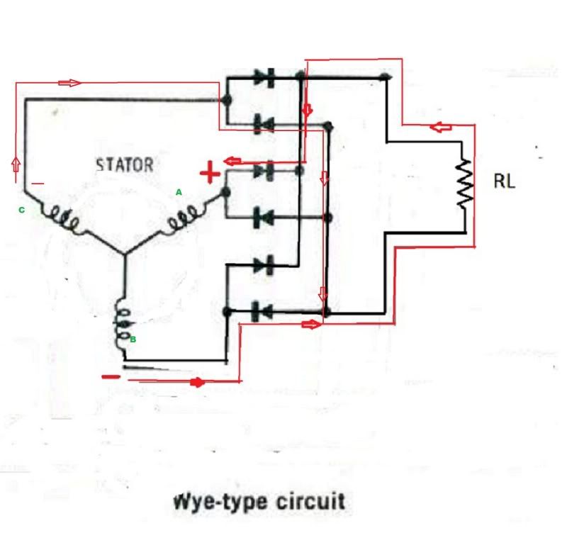
Now let’s consider the single phase stator configured as a y. A, B and C would all have the same potential at each of their outputs at all times. Current has no reason to flow though the load if there is no difference of potential from one side of the load to the other. In theory the output is zero. In reality the coils are not identical and there will be some small output. I would not describe this as working, just a silly way to connect it and you would be hard pressed to make it less efficient.
Now let’s connect the neutral to ground which on our bikes is also connected to the negative side of the load. Make the center negative and the ends of each coil positive. If you trace current you will see conduction through the load. When you change the center to positive and the ends to negative you will conduct through the diodes and directly back to the positive at the center without going through the load. These are direct short circuits save the small voltage drop across the forward biased diodes. This would be a half wave rectifier that shorts out the circuit during half of the input waveform. Again, I guess you say it works, but your status as a designer would be in serious question, until the alternator burns out and all doubt is removed.
Now let’s examine the Delta connection I guess the D-cell analogy would once again be drafted into use. Consider each coil as a D-Cell connected in series with one another. The negative on one end of the coil/battery is connected to the Positive on the next coil/battery. There is no resistance in this connection. In the single phase alternator, each junction between the coils would have the same potential compared to the other two. Why would current take a high resistance path out through the rectifier and load when a zero ohm path exists right there between the coils? Why would current flow from coils that have the same potential at each output? The answer is that it would not. Any "working" or output from the circuit is the result of differences in the coils. And again a silly way to connect it.
Bill has already proven to my mind that the best way to connect them is to put all three in phase coil sets in parallel, combining their near identical outputs and then connect the two wires to any two of three of the input wires on his rectifier/regulator, thereby using it as a single phase full wave bridge rectifier and a sophisticated regulator.
the image above with the three different forms of three phase alternators is one I recall seeing a long time ago in some of my texts. I don't think it was automotive or motorcycle specific and probably more for some sort of electronic application. the only one I have seen that I can recall in a motorcycle is the y type with no neutral. The Delta type I have seen in my career as a technician in the Navy. The last one with three separate unconnected coils is one I have never seen in use that I can recall.
Mike
[
If we look at the image that has the wave forms, and draw a vertical line from the positive peak of wave form A all the way to the bottom cutting through waveforms B and C. This line represents a snap shot of time. Now go to the end of coil A which I've labeled in the drawing below and put a positive on it's output to the rectifier. At that instant of time when checking where our line cuts through wave form B and C, we see they have negative potentials on them. So put negatives on the outputs of coils B and C. I have made these changes in the drawing below the waveforms and shown the path for current flow at that instant of time. It is as follows: from coil B through the bottom diode to the load. Through the load back to the top of the rectifier. Down to and through the third diode down to the positive potential at coil A. At the same instant of time current flows from coil C, to and through the second diode from the top. To the right and then straight down where at the tie point at the very bottom. It then joins with the current from coil B and follows the same path through the load to Coil A. Now draw a vertical line on the wave form C from the positive peak straight down. This represents the next instant in time I'll discuss. We see that coil C is now Positive and Coil A and B are negative. Relabel the drawing with a negative sign on coil A and B output and a positive on Coil C. Trace current through in the same way I did. Remember in doing so that current flows from negative to positive and flows against the arrow that the diodes symbol forms. when done with that you can move to the next instant for waveform B and in this way see how current flows through the circuit for a complete cycle. As this current passes through the load it will cause a voltage drop across it and power consumed by it.
The Delta circuit is a little harder to get your mind around and might be easier to do if you use time zero where the wave forms of each coil are at different potentials. Find the most positive point and the negative points will flow towards them. That is how they work. They need the paths for current created by the changing difference in potential "felt" at the output of each coil. Potentials are not "harvested" potentials (read voltage) are "felt" at various points throughout the circuit. These potentials don't move or flow, they cause current to flow. This current flow passing though resistance causes a voltage drop across the resistance (or impedance) and cause power to be consumed.
Now let’s consider the single phase stator configured as a y. A, B and C would all have the same potential at each of their outputs at all times. Current has no reason to flow though the load if there is no difference of potential from one side of the load to the other. In theory the output is zero. In reality the coils are not identical and there will be some small output. I would not describe this as working, just a silly way to connect it and you would be hard pressed to make it less efficient.
Now let’s connect the neutral to ground which on our bikes is also connected to the negative side of the load. Make the center negative and the ends of each coil positive. If you trace current you will see conduction through the load. When you change the center to positive and the ends to negative you will conduct through the diodes and directly back to the positive at the center without going through the load. These are direct short circuits save the small voltage drop across the forward biased diodes. This would be a half wave rectifier that shorts out the circuit during half of the input waveform. Again, I guess you say it works, but your status as a designer would be in serious question, until the alternator burns out and all doubt is removed.
Now let’s examine the Delta connection I guess the D-cell analogy would once again be drafted into use. Consider each coil as a D-Cell connected in series with one another. The negative on one end of the coil/battery is connected to the Positive on the next coil/battery. There is no resistance in this connection. In the single phase alternator, each junction between the coils would have the same potential compared to the other two. Why would current take a high resistance path out through the rectifier and load when a zero ohm path exists right there between the coils? Why would current flow from coils that have the same potential at each output? The answer is that it would not. Any "working" or output from the circuit is the result of differences in the coils. And again a silly way to connect it.
Bill has already proven to my mind that the best way to connect them is to put all three in phase coil sets in parallel, combining their near identical outputs and then connect the two wires to any two of three of the input wires on his rectifier/regulator, thereby using it as a single phase full wave bridge rectifier and a sophisticated regulator.
the image above with the three different forms of three phase alternators is one I recall seeing a long time ago in some of my texts. I don't think it was automotive or motorcycle specific and probably more for some sort of electronic application. the only one I have seen that I can recall in a motorcycle is the y type with no neutral. The Delta type I have seen in my career as a technician in the Navy. The last one with three separate unconnected coils is one I have never seen in use that I can recall.
Mike
[
Last edited by MotoMike on Sat Jul 16, 2011 5:02 pm, edited 3 times in total.
-
DewCatTea-Bob
- Posts: 2897
- Joined: Sun Nov 01, 2009 10:53 am
- Location: Near SE side of Lake Michigan
Poor Stator-winding Connection-method
MotoMike wrote:Have taken a bit of time to look over the three and single phase circuits most recently discussed here. I offer my thoughts on them.
If we look at the image that has the wave forms, and draw a vertical line from the positive peak of wave form A all the way to the bottom cutting through waveforms B and C. This line represents a snap shot of time. Now go to the end of coil A which I've labeled in the drawing below and put a positive on it's output to the rectifier. At that instant of time when checking where our line cuts through wave form B and C, we see they have negative potentials on them. So put negatives on the outputs of coils B and C. I have made these changes in the drawing below the waveforms and shown the path for current flow at that instant of time. It is as follows: from coil B through the bottom diode to the load. Through the load back to the top of the rectifier. Down to and through the third diode down to the positive potential at coil A. At the same instant of time current flows from coil C, to and through the second diode from the top. To the right and then straight down where at the tie point at the very bottom. It then joins with the current from coil B and follows the same path through the load to Coil A. Now draw a vertical line on the wave form C from the positive peak straight down. This represents the next instant in time I'll discuss. We see that coil C is now Positive and Coil A and B are negative. Relabel the drawing with a negative sign on coil A and B output and a positive on Coil C. Trace current through in the same way I did. Remember in doing so that current flows from negative to positive and flows against the arrow that the diodes symbol forms. As this current passes through the load it will cause a voltage drop across it and power consumed by it.
The Delta circuit is a little harder to get your mind around and might be easier to do if you use time zero where the wave forms of each coil are at different potentials. Find the most positive point and the negative points will flow towards them. That is how they work. They need the paths for current created by the changing difference in potential "felt" at the output of each coil. Potentials are not "harvested" potentials (read voltage) are "felt" at various points throughout the circuit. These potentials don't move or flow, they cause current to flow. This current flow passing though resistance causes a voltage drop across the resistance (or impedance) and cause power to be consumed.
Now let’s consider the single phase stator configured as a y. A, B and C would all have the same potential at each of their outputs at all times. Current has no reason to flow though the load if there is no difference of potential from one side of the load to the other. In theory the output is zero. In reality the coils are not identical and there will be some small output. I would not call describe this as working, just a silly way to connect it and you would be hard pressed to make it less efficient.
Now let’s connect the neutral to ground which on our bikes is also connected to the negative side of the load. Make the center negative and the ends of each coil positive. If you trace current you will see conduction through the load. When you change the center to positive and the ends to negative you will conduct through the diodes and directly back to the positive at the center without going through the load. These are direct short circuits save the small voltage drop across the forward biased diodes. This would be a half wave rectifier that shorts out the circuit during half of the input waveform. Again, I guess you say it works, but your status as a designer would be in serious question, until the alternator burns out and all doubt is removed.
Now let’s examine the Delta connection I guess the D-cell analogy would once again be drafted into use. Consider each coil as a D-Cell connected in series with one another. The negative on one end of the coil/battery is connected to the Positive on the next coil/battery. There is no resistance in this connection. In the single phase alternator, each junction between the coils would have the same potential compared to the other two. Why would current take a high resistance path out through the rectifier and load when a zero ohm path exists right there between the coils? Why would current flow from coils that have the same potential at each output? The answer is that it would not. Any "working" or output from the circuit is the result of differences in the coils. And an again a silly way to connect it.
Bill has already proven to my mind that the best way to connect them is to put all three in phase coil sets in parallel, combining their near identical outputs and then connect the two wires to any two of three of the input wires on his rectifier/regulator, thereby using it as a single phase full wave bridge rectifier and a sophisticated regulator.
the image above with the three different forms of three phase alternators is one I recall seeing a long time ago in some of my texts. I don't think it was automotive or motorcycle specific and probably more for some sort of electronic application. the only one I have seen that I can recall in a motorcycle is the y type with no neutral. The Delta type I have seen in my career as a technician in the Navy. The last one with three separate unconnected coils is one I have never seen in use that I can recall.
Mike
[
____ Thanks a lot again Mike ! _ As it seems your brain-power has brought even more revelation to the table...
__ Once again you've posted too much to absorb all at once,
and also brought-fourth notions into my head which were previously uninspired.
While I was considering such as "bottle-necks" as the main-suspect for the poor outcome, you've reviewed ANOTHER (independent) culprit which seems to vastly SUPERSEDE that which I was willing to give all the credit to (for the disappointing results).
That being that the Delta-arrangement (as it has been depicted), is very potentially just ONE BIG 'SHORT' circuit ! _ And it's so extremely very obvious TOO ! _ If only I hadn't brushed-past Bruce's post about his VW-alt, and thought-out a worthy amount concerning his point about finding diodes directly-connected internally at all the ends of each of the stator-windings ! _ How in heck could such have any chance of working well enough, without any diodes placed in such fashion ?!? _ I must be getting too stupid, as I overlooked such a very obvious short-coming ! - (see added pic)
This is got to be my greatest blunder ever !
I saw the Delta-scheme in a couple places and so naturally just assumed that it was an established workable scheme (which I had been unfamiliar with). _ So thus understandably skipping-over the otherwise quite obvious basics, I went-on to determine that since it must work for 3-phase, then why not single-phase as well !?
Well now I see that not only can't it work for single-phase (with OUR three-sections), it's also a very questionable circuit even for true '3-phase' !!! - As it would still encounter the very same issue although at a much reduced amount, (without the internal diodes added).
It just goes to show that you can't trust what you find & see on the net !
__ I must now obviously take-back what I've said previously (in recent posts) about the Delta-type scheme being in the same class as the "B" type, since it's an obviously malfunked scheme, (and even the Y-star type must be superior !).
____ Much thanks to Mike, and Bruce as well, not to mention Bill,, and I'm very-sorry Bill for ever suggesting those recent tests which you bothered to try-out, based on that obviously stupid delta-scheme.
It's all been one extraordinary bad-dream !
You do not have the required permissions to view the files attached to this post.
PLEASE NOTE... If this-post is not-yet signed-off with '-Bob', then I'm still in the process of completing it,, and if not also included with 'DCT' near bottom as well, then I may edit this post's wording at a later time. - Dct.Bob
-
wcorey
- Posts: 323
- Joined: Sun Jan 31, 2010 1:50 am
- Location: MA USA
Re: 6volt or 12 volt?
Still scheming and plotting on converting the 'three section stator' to three phase...
I thought of a potential solution, an 8 magnet rotor and re wiring of the stator so the two coils of each pair are 180 degrees
opposite each other (instead of 60 degrees apart/next to each other) and the wiring/polarity on one is reversed (since they're wound in opposite directions and unlike the 'normal' configuration, would hit
the same polarity magnet at the same time).
Am I explaining that in a comprehensible manner? Anyone care to imagine and rotate that setup around in their head to see if I'm missing something obvious? Don't want to go to the trouble to draw it, or worse, fabricate it, if it's a blatant no go.
What I can't seem to reconcile is if there's a difference between a coil that's wound in a given direction and one that's connected up in a given (pos/neg) direction (to obtain a given polarity). My understanding is that if a coil is wound in one direction, when power is applied or produced, it has a particular polarity that would reverse if either it was wound in the opposite direction or if the power connections were reversed (or also if the magnet were reversed). It seems that it's one polarity or the other no matter the method of getting there and the end result would be effectively the same... Yes?
Bill
Return to “Ducati Singles Main Discussions (& How to Join)”
Who is online
Users browsing this forum: No registered users and 84 guests