" I would have to say this drawing is more a logical arrangement
, and best used to organize schematic drawings in a logical manner.
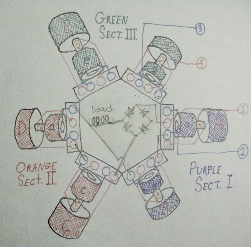
Looking at my stator, this doesn't match exactly how the leads are arranged literally,
____ In that case, your drawing will still not be fully helpful to Bill (for figuring-out exactly what's what).
It's too bad that Ducati didn't construct all their dual-spools consistently in some particular logical manor.
" To wire the stator is still going to take some continuity testing just to see where everything is going, but to depict it in the drawing the way it really is would further confuse things (logically) for schematic drawings. Bill had noted that there was one spool that was backwards or reversed and depicted such in his drawing,
____ I understand what you mean about how an actual/real-life depiction would have a non-logical/screwed-up and thus confusing & disconcerting appearance, but still, that's the kind of representation which is actually needed.
" Here is a version of drawing depicting the seperate sections I think the way you described. "
____ That's right...
Rather than having to refer to each 'coil-spool pair' as: "Aa/Bb" or "Cc/Dd" , now that we have a third segment/section -( Ee/Ff ), it's just more straight-forward to simply refer to each as: 'se.I' ; 'se.II' ; & 'se.III' .
Forward-Cheers,
-Bob
n-c alternator modifications: discussion and testing
Moderator: ajleone
-
DewCatTea-Bob
- Posts: 2897
- Joined: Sun Nov 01, 2009 10:53 am
- Location: Near SE side of Lake Michigan
Drawn Stator Lead-ends vs. their Actual Physical-location
PLEASE NOTE... If this-post is not-yet signed-off with '-Bob', then I'm still in the process of completing it,, and if not also included with 'DCT' near bottom as well, then I may edit this post's wording at a later time. - Dct.Bob
-
ecurbruce
- Posts: 317
- Joined: Fri Apr 01, 2011 12:43 am
- Location: Hurricane mills TN
Re: 6volt or 12 volt?
Bob & Bill wrote "__ One thing which I need clarified first though, is exactly what test-setup/arrangement is referred-to by: "series/parallel" (in the last two groupings) ?
Like this one but 1-4 and 2-3 is A/B and C/D;
Bill"
Bill, can you draw (insert) this schematic into the multicolored drawing that I supplied Sat. June 18 1031 PM? I think I'm lost on this one.
Also, Bill on page 31, Fri. June 17 2:39 AM, you posted test results of the 3 sets of two coils (ohms and watts). I wonder if you have the voltages for those tests in your photos without having to go back and re- test those? Dont need to see the photos, just the numbers...
Thanks, Bruce.
-
DewCatTea-Bob
- Posts: 2897
- Joined: Sun Nov 01, 2009 10:53 am
- Location: Near SE side of Lake Michigan
Fully-drawn Stator (with Dual half-wave
" Bill, can you draw (insert) this schematic into the multicolored drawing that I supplied Sat. June 18 1031 PM? I think I'm lost on this one. "
____ Bruce, when you wish to identify a particular post by date & time, ya have to obtain that specific data when you're NOT logged-in,, cuz when you log-in, then all the stated times convert-over to YOUR-own particular time-zone, (which may then of course likely throw times out of sinc).
____ Also, I doubt that Bill is very interested in spending any time messing-around with any drawings, (unless he's uniquely qualified).
So I should be the one to take-on the task.
Stay-Tuned,
-Bob
PLEASE NOTE... If this-post is not-yet signed-off with '-Bob', then I'm still in the process of completing it,, and if not also included with 'DCT' near bottom as well, then I may edit this post's wording at a later time. - Dct.Bob
-
ecurbruce
- Posts: 317
- Joined: Fri Apr 01, 2011 12:43 am
- Location: Hurricane mills TN
Re: 6volt or 12 volt?
Bob says____ "Bruce, when you wish to identify a particular post by date & time, ya have to obtain that specific data when you're NOT logged-in,, cuz when you log-in, then all the stated times convert-over to YOUR-own particular time-zone, (which may then of course likely throw times out of sinc)."
Oh, yea, sorry bout that.
Bill, the tests that I referred to (that I would like to see the voltages ) are the ones on page 31 that you tested at 6000 RPM. You posted the ohms and the watts.
If you could insert the schematic into the drawing that I last submitted that is colored as per the sections I, II, III.
Thanks again, Bruce.
-
ecurbruce
- Posts: 317
- Joined: Fri Apr 01, 2011 12:43 am
- Location: Hurricane mills TN
Re: 6volt or 12 volt?
Bob says"____ Also, I doubt that Bill is very interested in spending any time messing-around with any drawings, (unless he's uniquely qualified).
So I should be the one to take-on the task.
OK, did you understand what I was asking for?
So I should be the one to take-on the task.
OK, did you understand what I was asking for?
-
wcorey
- Posts: 323
- Joined: Sun Jan 31, 2010 1:50 am
- Location: MA USA
Re: 6volt or 12 volt?
___ I'm afraid I'm lost as to why you needed "six" wires ...
Two for each section. How else would it be done to accommodate all these different combinations of tests?
Been very busy so the flow of data has been slow but since I’m very impatient to see how things will progress, I fit in a quick but very dense round of tests with dual and triple full wave rectification on the 'grand series, stock series/parallel' type arrangements. Lots of raw data (pics of running tests) but not enough time to organize, tabulate and transcribe it all. I believe this to be getting pretty close the culmination of all our work so on one hand I hesitate to half-ass report it but on the other hand hate to hold out until I have time to do it right. Half-ass wins, I guess...
Had to yet again add resistors to the load array to be able to get two simultaneous equal loads through the range of tests, I drew the line there however, doing three seemed redundant and would be a pain for many reasons. I also omitted doing vac readings as these are apparently of little use at this point. It's relatvely time consuming to find the peak working load range so I did some jumping around which resulted in some redundant and at times random testing on both section I with section II and section I with section III, the numbers are a bit variant on each but to save time I'm reporting whatever combination I need to get test results done at each given load. So I wouldn’t get too fussy about a couple watts as I’m also still seeing some slightly inconsistent readings.
Dual full wave rectification, 'grand series, stock series/parallel', separated outputs.
(Two sections (of two spools each) run simultaneously, each with full wave rectification, two outputs/loads.)
3450 rpm, each 'pair' of sections is one test.
sec I, 1ohm-----4.2a----4.3vdc----18.1w
sec III, 1ohm---4.1a----4.3vdc----17.6w
sec I, 2ohm-----3.4a----6.9vdc----23.5w
sec II, 2ohm----3.3a----6.7vdc----22.1w
sec I, 3ohm-----2.9a----8.6vdc----25.2w
sec II, 3ohm----2.7a----8.2vdc----22.1w
sec I, 4ohm-----2.5a----9.7vdc----24.3w
sec III, 4ohm---2.4a----9.5vdc----22.8w
sec I, 5ohm-----1.9a----11.0vdc----21.0w
sec II, 5ohm----1.7a----10.1vdc-----17.2w
6k rpm
sec I, 1ohm-----4.9a----4.9vdc----24.0w
sec III, 1ohm---4.9a----5.1vdc----27.4w
sec I, 2ohm-----4.4a----8.9vdc----39.2w
sec II, 2ohm----4.1a----8.5vdc----34.9w
sec I, 4ohm-----3.6a----14.0vdc----50.4w
sec II, 4ohm----3.6a----14.3vdc----51.5w
sec I, 5ohm-----3.2a----15.9vdc----50.9w
sec III, 5ohm---3.2a----16.0vdc----51.2w
sec I, 6ohm-----3.0a----17.3vdc----51.9w
sec III, 6ohm---2.8a----17.2vdc----48.4w
sec I only, 2 ohm---3.3a----16.2vdc----53.5w
Sections I and III run simultaneously, each with full wave rectification, combined outputs.
3450 rpm
1 ohm----6.8a----7.0vdc------47.6w
2 ohm----4.7a----9.7vdc-----45.6w
3ohm----3.6a----10.9vdc----39.2w
4ohm----2.4a----11.9vdc----28.6w
5ohm----2.0a----12.3vdc----24.6w
6k rpm
1ohm----8.7a----8.9vdc------77.4w
2ohm----7.0a----14.3vdc----100.1w
3ohm----5.6a----17.0vdc----95.2w
4ohm----4.6a----18.6vdc----85.6w
5ohm----3.9a----19.6vdc----76.4w
All three sections run simultaneously, each with full wave rectification, combined outputs.
3450 rpm
1 ohm----8.1a----8.4vdc------68w
2 ohm----5.2a----10.6vdc----55.1w
3ohm----3.7a----11.5vdc----42.6w
4ohm----2.9a----12.0vdc----34.8w
6k rpm
1ohm----11.1a---11.6vdc----128.8w
2ohm----8.2a----16.9vdc----138.6w
3ohm----6.3a----19.4vdc----122.2w
4ohm----5.1a----20.8vdc----111.2w
Bill
Last edited by wcorey on Mon Aug 15, 2011 5:20 pm, edited 1 time in total.
-
DewCatTea-Bob
- Posts: 2897
- Joined: Sun Nov 01, 2009 10:53 am
- Location: Near SE side of Lake Michigan
Re: 6volt or 12 volt?
By: ecurbruce...
" OK, did you understand what I was asking for? "
____ Maybe not exactly... I thought you needed your colorized stator-drawing to be combined with the related rectifier-circuit which Bill was testing !? _ I've now done that task !
Please let me know if you had meant anything much different.
__ The main difference between my depicted power-circuit and that which you were asking Bill about, is his related test (at the time), was of just section-I & section-II (while connected in the 'straight-series' arrangement), whereas my new drawing indicates all three sections (I & II & III) to be tested that way.
You do not have the required permissions to view the files attached to this post.
PLEASE NOTE... If this-post is not-yet signed-off with '-Bob', then I'm still in the process of completing it,, and if not also included with 'DCT' near bottom as well, then I may edit this post's wording at a later time. - Dct.Bob
-
wcorey
- Posts: 323
- Joined: Sun Jan 31, 2010 1:50 am
- Location: MA USA
Re: 6volt or 12 volt?
My version, the usual disclaimer of not being sure of actual polarities.
Do you need all three sections? VAC? I did a large number of tests in that round (82) and didn't take the time to fish out the exact ones the data from the other post was based on, this is another set, should be more or less equivalent.
Full wave, 6k rpm, single section (II, C/D)
2ohm----4.8a----9.7vdc-----46.6w
3ohm----4.2a----12.9vdc----54.2w
4ohm----3.8a----15.1vdc----57.3w
5ohm----3.5a----17.4vdc----60.9w
6ohm----3.0a----18.1vdc----54.3w
7ohm----2.8a----19.2vdc----53.8w
Bill
Bill, the tests that I referred to (that I would like to see the voltages ) are the ones on page 31 that you tested at 6000 RPM. You posted the ohms and the watts.
Do you need all three sections? VAC? I did a large number of tests in that round (82) and didn't take the time to fish out the exact ones the data from the other post was based on, this is another set, should be more or less equivalent.
Full wave, 6k rpm, single section (II, C/D)
2ohm----4.8a----9.7vdc-----46.6w
3ohm----4.2a----12.9vdc----54.2w
4ohm----3.8a----15.1vdc----57.3w
5ohm----3.5a----17.4vdc----60.9w
6ohm----3.0a----18.1vdc----54.3w
7ohm----2.8a----19.2vdc----53.8w
Bill
Last edited by wcorey on Tue Jun 21, 2011 6:29 am, edited 2 times in total.
-
DewCatTea-Bob
- Posts: 2897
- Joined: Sun Nov 01, 2009 10:53 am
- Location: Near SE side of Lake Michigan
Which is What, or What is Which ??
By: wcorey...
" My version, "
____ I've just looked-over Bill's drawing of the rectifier-circuit which he placed inside Bruce's stator-drawing...
Aside from a couple missing (likely just overlooked) circuit-connections (between terminal-points), I believe that Bill's depicted circuit intends to indicate that both section-I & section-II are each separately half-wave rectified, and both of the two winding-&-diode circuits are combined in a PARALLEL scheme.
And that's what's different from my-own version, as mine was meant to show section-I & section-II connected-together in a 'series' scheme, (as indicated by the schematic-diagram which Bill had posted, in response to my inquiry).
So it obviously seems that at least one of the three of us has been misunderstood and/or misunderstood one (or both) of the other two. _ Or something like that, anyhow !
__ I guess that ether Bruce has to clarify exactly what he had wanted to know specifically, or perhaps Bill had not really been fully clear enough on exactly what the actual circuit-arrangement actually was, (although the posted scheme should've made it clear that se.I & se.II were still in 'series', [not parallel]).
____ I now think I know how the misunderstanding came to be.....
(The side-benefit of this, is we got Bill to scheme a circuit which hadn't yet been done.)
Cleared-Cheers,
-Bob
" My version, "
____ I've just looked-over Bill's drawing of the rectifier-circuit which he placed inside Bruce's stator-drawing...
Aside from a couple missing (likely just overlooked) circuit-connections (between terminal-points), I believe that Bill's depicted circuit intends to indicate that both section-I & section-II are each separately half-wave rectified, and both of the two winding-&-diode circuits are combined in a PARALLEL scheme.
And that's what's different from my-own version, as mine was meant to show section-I & section-II connected-together in a 'series' scheme, (as indicated by the schematic-diagram which Bill had posted, in response to my inquiry).
So it obviously seems that at least one of the three of us has been misunderstood and/or misunderstood one (or both) of the other two. _ Or something like that, anyhow !
__ I guess that ether Bruce has to clarify exactly what he had wanted to know specifically, or perhaps Bill had not really been fully clear enough on exactly what the actual circuit-arrangement actually was, (although the posted scheme should've made it clear that se.I & se.II were still in 'series', [not parallel]).
____ I now think I know how the misunderstanding came to be.....
____ Bruce, it seems you didn't make it clear enough that your (one single) post was concerning TWO considerably different inquires, concerning two SEPARATE posts by Bill.ecurbruce wrote:Bob & Bill wrote
"__ One thing which I need clarified first though, is exactly what test-setup/ arrangement is referred-to by: "series/parallel" (in the last two groupings) ? "wcorey wrote:Like this one but 1-4 and 2-3 is A/B and C/D;
Bill"
Bill, can you draw (insert) this schematic into the multicolored drawing that I supplied Sat. June 18 1031 PM? I think I'm lost on this one.
(The side-benefit of this, is we got Bill to scheme a circuit which hadn't yet been done.)
Cleared-Cheers,
-Bob
You do not have the required permissions to view the files attached to this post.
PLEASE NOTE... If this-post is not-yet signed-off with '-Bob', then I'm still in the process of completing it,, and if not also included with 'DCT' near bottom as well, then I may edit this post's wording at a later time. - Dct.Bob
-
DewCatTea-Bob
- Posts: 2897
- Joined: Sun Nov 01, 2009 10:53 am
- Location: Near SE side of Lake Michigan
Re: 6volt or 12 volt?
By: wcorey...
" Two for each section. How else would it be done to accommodate all these different combinations of tests? "
____ Well assuming that all three sections remain as part of the stator, then besides the outer pair of wires (of which one is at the beginning of se.I, and the other, at the end of se.III),, then a couple of tap-wires are needed... a 3rd-wire is thus required to be located between se.I & se.II, and a 4th-wire located between se.II & se.III .
Those two added tap-wires ought to be able to be used for testing the neighboring sections on either side (of each). _ So I can understand temporarily soldering-in those two added tap-wires, (but don't see any need for two more besides).
" I believe this to be getting pretty close the culmination of all our work so on one hand I hesitate to half-ass report it but on the other hand hate to hold out until I have time to do it right. "
____ As un-supremely done as this thread had become, we might as well have raw stuff now, as opposed to combed stuff later !
" Had to yet again add resistors to the load array to be able to get two simultaneous equal loads through the range of tests, "
____ Just goes to show that you're even more-so uniquely capable of doing such test-work, Bill !
" I drew the line there however, doing three seemed redundant and would be a pain for many reasons. "
____ By: "doing three" , I assume you mean that after using three separate FW.rect-blocks (to full-wave rectify each of the separate sections -[se.I & se.II & se.III]), you then don't wish to go-through the pain of wiring-up three separate loads (to go with) !? ...
Well if you did go-ahead & do it that way, then you'd have to sum-up the individual power-consumptions of all three loads, added together,, in order to get the TOTAL power-output !
But it really doesn't have to be done that way... Rather, once the three separate stator-sections have been separately rectified, ((NOW I see why you might need "6" wires !)), the outputs of ALL three FW.rect.blocks can be combined & used against just one (high wattage!) load.
" Dual full wave rectification, 'grand series, stock series/parallel', separated outputs.
(Two sections (of two spools each) run simultaneously, each with full wave rectification, two outputs/loads.)
3450 rpm, each 'pair' of sections is one test. "
____ So in other words, while doing ONE test-run, you're actually performing TWO (fairly separate) test-circuits simultaneously both at once, correct?
" sec I, 1ohm-----4.2a----4.3vdc----18.1w
sec III, 1ohm---4.1a----4.3vdc----17.6w "
____ The combined-total of these two together (in parallel) ought-to equate to
.5-ohms & 35.7-watts.
sec I, 2ohm-----3.4a----6.9vdc----23.5w
sec II, 2ohm----3.3a----6.7vdc----22.1w
" sec I, 3ohm-----2.9a----8.6vdc----25.2w
sec II, 3ohm----2.7a----8.2vdc----22.1w
____ Same as I just stated directly-above, except instead of "ought-to", I rather state 'should' equate to
1.5-ohms & 47.3-watts.
Because these circuits behave more predictably when their working-impedance is matched to the load-resistance.
sec I, 4ohm-----2.5a----9.7vdc----24.3w
sec III, 4ohm---2.4a----9.5vdc----22.8w
sec I, 5ohm-----1.9a----11.0vdc----21.0w
sec II, 5ohm----1.7a----10.1vdc-----17.2w
6k rpm
sec I, 1ohm-----4.9a----4.9vdc----24.0w
sec III, 1ohm---4.9a----5.1vdc----27.4w
sec I, 2ohm-----4.4a----8.9vdc----39.2w
sec II, 2ohm----4.1a----8.5vdc----34.9w
sec I, 4ohm-----3.6a----14.0vdc----50.4w
sec II, 4ohm----3.6a----14.3vdc----51.5w
sec I, 5ohm-----3.2a----15.9vdc----50.9w
sec III, 5ohm---3.2a----16.0vdc----51.2w
sec I, 6ohm-----3.0a----17.3vdc----51.9w
sec III, 6ohm---2.8a----17.2vdc----48.4w
sec I only, 2 ohm---3.3a----16.2vdc----53.5w
Sections I and III run simultaneously, each with full wave rectification, combined outputs.
3450 rpm
1 ohm----6.8a----7.0vdc------47.6w
2 ohm----4.7a----9.7vdc-----45.6w
3ohm----3.6a----10.9vdc----39.2w
4ohm----2.4a----11.9vdc----28.6w
5ohm----2.0a----12.3vdc----24.6w
6k rpm
1ohm----8.7a----8.9vdc------77.4w
2ohm----7.0a----14.3vdc----100.1w
3ohm----5.6a----17.0vdc----95.2w
4ohm----4.6a----18.6vdc----85.6w
5ohm----3.9a----19.6vdc----76.4w
All three sections run simultaneously, each with full wave rectification, combined outputs.
3450 rpm
1 ohm----8.1a----8.4vdc------68w
____ Now here indeed is the golden-fleece, that which all your testing has been leading us towards.
It's not very likely that a better arrangement for max.power-output could be concocted.
__ Bill, this outcome ought to be good enough for your-own purpose.
Could you wind your-own (roughly)- 1.3 & .7 ohm test-loads?
____ Bruce, do you now see what ought to be tried with a rewind-job ?
____ If you guys don't next ask the right questions,
I'll explain what questions ought be addressed next.
2 ohm----5.2a----10.6vdc----55.1w
3ohm----3.7a----11.5vdc----42.6w
4ohm----2.9a----12.0vdc----34.8w
6k rpm
1ohm----11.1a---11.6vdc----128.8w
2ohm----8.2a----16.9vdc----138.6w
3ohm----6.3a----19.4vdc----122.2w
4ohm----5.1a----20.8vdc----111.2w
____ I'll get back to finishing this post later.
PLEASE NOTE... If this-post is not-yet signed-off with '-Bob', then I'm still in the process of completing it,, and if not also included with 'DCT' near bottom as well, then I may edit this post's wording at a later time. - Dct.Bob
Return to “Ducati Singles Main Discussions (& How to Join)”
Who is online
Users browsing this forum: No registered users and 132 guests