n-c alternator modifications: discussion and testing

Ducati single cylinder motorcycle questions and discussions, all models. Ducati single cylinder motorcycle-related content only! Email subscription available.
Moderator: Morpheus

Moderator: ajleone

wcorey
Posts: 323
Joined: Sun Jan 31, 2010 1:50 am
Location: MA USA

n-c alternator modifications: discussion and testing

Postby wcorey » Fri May 20, 2011 12:52 am

-
<EDIT> August 29 2011

The content of this thread originated in the, ‘6volt or 12volt?’ thread, which has been moved to it’s own space and this one then renamed to better reflect it’s purpose.

As is typical, the material that has remained here sprouted up spontaneously as an offshoot of yet another sidetrack in the same thread, which was a discussion on the relationship between the stock 6-pole alt and the stock n-c R/R (and that one really started in yet another thread, "six coil alternator in a narrow case 250").

What’s here is a discussion of how to increase the power output of a narrow case 6-pole alternator that includes actual bench testing of various modifications of what started as a 4 coil n-c stator and progressed to various rewiring schemes, installing an additional two coils and still further to modified/adapted modern Denso alternators.

This thread consists of 350+ posts, is lacking in organization, and can be difficult to follow (I backed it up to a Word doc and at that time ended up as 523 pages, 926,825 characters).
It wasn’t really planned, it just happened, so of course has its share of mistakes, failures and dead ends, as well as revelations and successes. It was largely a group effort by DCT-Bob, ecurbruce, MotoMike and myself with occasional appearances by Bevel bob and machten. I look at this simply as an archive, other more specific and functional threads are being created to organize, continue and maybe conclude some of the topics started here. I'll add links here as those works are completed.

What follows as first post here is when I joined in to what was becoming a bit of a contentious discussion and at the time was 8 or so pages into the original thread.


I've been following this thread closely hoping to absorb at least a bit of it but unfortunately the vast majority goes way over my head. I greatly appreciate the efforts put forth to simplify things for us 'uninitiated' types but it has obviously spun out of control in that particular aspect. Every time I think I 'get it' some counterpoint comes up that confounds me yet again. It's like being a juror on a court case where each side is of course presenting a view only advantageous to their side of the argument. I would really like to jump ahead to the 'closing statements' that synopsizes each view, then have the judge explain it all to me in laymen terms, then listen to the CNN analysis. :lol:

However, the more practical 'hands on' aspects of getting the most out of the stock alternator are still within my realm of comprehension and all this has gotten me interested enough to put my test setup back in use.

I previously didn't put much effort into the stock setup as my preliminary tests were fairly disappointing compared to the results with the more modern stuff I was also playing with and my primary goal was to simply outfit my project bike with something that would run a 55w headlight. The number of threads on the subject and plethora of different possible methods were making my head spin and I never felt I got a handle on it so I basically ignored it all and started from scratch on my own terms.

The few basic numbers I previously came up with for the '60w' n-c alternator were specifically at Bob's request and I never got around to set it up again with that alternator to satisfy all his inquiries. Something I also never did was to split the output or even lift the grounded coil ends. Yet another thing I neglected was to load test the straight AC output, I always had at minimum a generic rectifier, as Bob had voiced concern that the random R/R's I was using would skew the results in an indeterminable way.

I still have things set up so as to take reasonable requests for further testing as I'm sure I'm missing some important and obvious aspects...
I don't have a stock R/R so that still isn't an option but I do have many others, from generic rectifier blocks and zener's to 3 ph mosfet R/R's and many things between.

Well anyway, I've some new numbers and they leave me scratching my head a bit.
Not sure how simply grounding/ungrounding the ends would have any affect but it seems to be part of the discussion so I've tried it and included it in the results. I can also take current readings if needed.

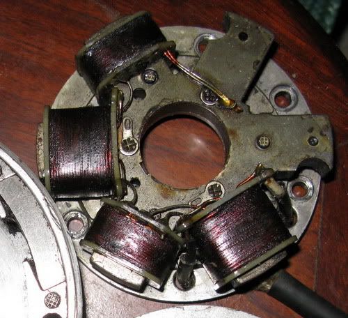
Output readings straight off the stator at 3450 RPM, n-c '60w' 4 coil stator, 6 pole rotor. Hopefully I got my numbers right, I never seem to think to write things down, lol.

AC output, no load, stock 'two wire' setup with ends grounded; 31.6vac

AC output, no load, stock 'two wire' setup with ends ungrounded; 31.6vac

AC output, load=55w headlight, stock 'two wire' setup with ends ungrounded; 11.6vac

AC output '4 wire setup' (coil ground ends lifted and separated with wires running out), no load; 15.8vac (connecting meter to either individual 'side' (or pair of wires))

AC output '4 wire setup' (coil ground ends lifted and separated with wires running out), load=55w headlight; 12.1vac " "

So I am appearing to get more output from each individual "separated side" than from the combined total of the two run as stock (grounded) or with the grounds connected/lifted.
If I had though I'd get this result in the beginning, it may have saved me a shitload of time/money/work playing with the new stuff, as I would likely have just used the stocker and not gone any further :(

I haven't yet tried them in parallel (simultaneously) with a load on each, I'll have to dig up another headlight...
Also haven't run it for any length of time and hit it with a temp gun, seems like temperature could be a good relative indicator of duty cycle for the various configurations.

Bill
Last edited by wcorey on Wed Aug 31, 2011 5:46 pm, edited 5 times in total.

DewCatTea-Bob
Posts: 2897
Joined: Sun Nov 01, 2009 10:53 am
Location: Near SE side of Lake Michigan

Bill's n-c alternator output test results

Postby DewCatTea-Bob » Fri May 20, 2011 1:38 am

" The few basic numbers I previously came up with for the '60w' n-c alternator were specifically at Bob's request "

____ Yes, and thanks again for that Bill !
I believe that you then found results which indicated your 4 core-coil stator (with both alt.windings circuited in series-fashion) produced about 45-watts at your test RPM.


" Something I also never did was to split the output or even lift the grounded coil ends. "

____ The particular testing you were doing did not require the stator-winding tip-ends (from each alt.winding) to be 'ungrounded' -(lifted & isolated) from the stator-plate, since the stator-plate was taken off & away from any normally related 'Ground' circuit !
Also, (after unsoldering that connection), splitting-up the outputs (of the two separate alt.windings) so that each could be tested individually, is in my-OWN opinion, a worth-while test-experiment.


" Yet another thing I neglected was to load test the straight AC output, "

____ Yes, doing that would be the appropriate way to help rate the actual alternator itself.


" I always had at minimum a generic rectifier, as Bob had voiced concern that the random R/R's I was using would skew the results in an indeterminable way. "

____ Well put, except I meant that it was possible that your chosen R.R-units COULD possibly hurt results otherwise achieved with just a suitable FW-bridge-block.


" I still have things set up so as to take reasonable requests for further testing as I'm sure I'm missing some important and obvious aspects... "

____ That's fantastically gracious of you Bill !
And one "aspect" of your testing that's not quite fair for getting proper test-results, is your use of such a powerful light-bulb... As they draw current in a nonlinear manor as they heat-up ! _ So better to use a power-resistor. _ However, if a voltmeter is left connected in parallel with the bulb, while an amp-meter keeps track of amperage through it's filament, then that should be well enough.

" I don't have a stock R/R so that still isn't an option but I do have many others, from generic rectifier blocks and zener's to 3 ph mosfet R/R's and many things between. "

____ It ought be interesting to compare the various possible effects which different R.R-units have, compared to an ordinary FW.bridge-block.


" Not sure how simply grounding/ungrounding the ends would have any affect but it seems to be part of the discussion so I've tried it and included it in the results. "

____ If the stator-plate is still grounded to the 'Ground' (of the motor-case & bike), then it would make a big difference, as there could then be shortened circuits, depending on rectifier-circuit types.


" AC output, load=55w headlight " "; 11.6vac "

____ I gather that this test indicates that the test-bulb had 11.6 AC-volts across it when connected to the original pair of (yellow) wire-leads, (while the internal lead-ends of the two alt.windings remained connected) ?


" AC output '4 wire setup' (coil ground ends lifted and separated with wires running out), no load; 15.8vac (either individual 'side' (or pair of wires)) " load=55w headlight; 12.1vac "


____ I gather that this test indicates that the test-bulb had 12.1 AC-volts across it when connected to one original (yellow) wire-lead and the corresponding opposite lead-end of just one of the two alt.windings ?


" So I am appearing to get more output from each individual "separated side" than from the combined total of the two run as stock (grounded) or with the grounds connected/lifted. "

____ Paying attention now Mike ?


" I haven't yet tried them in parallel (simultaneously) with a load on each, "

____ Before you try running separate loads on each of the two now completely separated alt.windings, you ought confirm the power-consumption of your test-bulb by measuring current-flow through the bulb-filament, along with keeping track of the voltage across it,, testing just one alt.winding at a time.
And then afterwords try running both separate circuits at once.
__ After the AC testing has been all confirmed, then doing all the same tests with the outputs first converted to DC (with just a mere FW.bridge-block rectifier-circuit), would be useful for making-sure that all is addin-up as it should.
Then you could also try running both alt.winding DC-outputs truely in parallel, for what should be interesting results.


" Also haven't run it for any length of time and hit it with a temp gun, seems like temperature could be a good relative indicator of duty cycle for the various configurations. "

____ Useful idea ! _ After it's been run long enough to reach max.operating-temp (for an established figure), then such measurements could be useful for comparing operation of various R.R.units.
However that would no-doubt take some extensive testing.


____ Thanks a lot for bringing new life-blood to the tread, Bill !


Hopeful-Cheers,
-Bob
PLEASE NOTE... If this-post is not-yet signed-off with '-Bob', then I'm still in the process of completing it,, and if not also included with 'DCT' near bottom as well, then I may edit this post's wording at a later time. - Dct.Bob

MotoMike
Posts: 487
Joined: Wed Aug 04, 2010 3:40 am

Re: 6volt or 12 volt?

Postby MotoMike » Fri May 20, 2011 3:38 am

Bill

thanks very much for your efforts. finding a resistor to handle 55 watts or more will be fun. a light bulb is a common device for such tests so long as you monitor voltage and current as bob has suggested. can you make some drawings showing the various connections associated with the readings. If you could take current readings it would really help to finish the puzzle. I know it is one of those minds eye things where you know what you mean, but I am not getting how they are connected. Incidentally I respect your attitude towards tackling what some would find a very daunting task. designing and building the jig and test equipment to do your work are no small task.

Bob, trying to pay attention, but think I'd like some drawings of the various connections associated with each of the quoted figures. I am lost as to just how these are connected.
So will reserve an opinion till I can see what is going on.

without knowing the current figures on each, it is hard to say for sure what is going on. I'm assuming that 55w bulb is a 12 volt bulb? If so the only measurement I saw that would indicate a somewhat correct wattage was the 55 watt bulb across a 12.1 volt vac source. that would be 55watts.

I don't think you have enough info in other examples using that bulb without the voltage across and current through to make an informed assessment.


thanks
Mike

wcorey
Posts: 323
Joined: Sun Jan 31, 2010 1:50 am
Location: MA USA

Re: 6volt or 12 volt?

Postby wcorey » Fri May 20, 2011 7:36 am

Ok, round two... I will edit my last post to better clarify the results, for some reason the way I spaced the " " didn't carry over to the actual post.

" AC output, load=55w headlight " "; 11.6vac "

____ I gather that this test indicates that the test-bulb had 11.6 AC-volts across it when connected to the original pair of (yellow) wire-leads, (while the internal lead-ends of the two alt.windings remained connected) ?


Correct.


" AC output '4 wire setup' (coil ground ends lifted and separated with wires running out), no load; 15.8vac (either individual 'side' (or pair of wires)) " load=55w headlight; 12.1vac "


____ I gather that this test indicates that the test-bulb had 12.1 AC-volts across it when connected to one original (yellow) wire-lead and the corresponding opposite lead-end of just one of the two alt.windings ?


Correct again.


If you could take current readings it would really help to finish the puzzle.


No problem on current readings but if you know the voltage and wattage doesn't that also tell you current?


I know it is one of those minds eye things where you know what you mean, but I am not getting how they are connected.


Sorry Mike, I'm getting from this I wrongly assumed you were familiar with the physical layout of this particular stator? (or is it just the way I'm describing connecting from the stator to the load?) I'll try to describe it as I see it, though not sure if it will make any more sense than my last post.
There are six core positions, two unpopulated then four coils in a row. It appears that the four are wound in sequence with two equal 'parallel' windings (not sure if they're wound in opposite directions) so there are two wires coming out of the first coil and two from the fourth. The two from one end are the outputs ('two wire setup') and the other two are grounded together to the core, effectively eight windings, grounded in the center. So when the ends are ungrounded, separated and wires added to each, you get the 'four wire setup', obviously creating (the option of) two separate sets of four windings. I take one reading from the stock series setup with the two outputs on one end going to the load with the other two together/grounded, the other reading using one output lead from either end. Getting the same values from either set of separated windings.
The bulb is 12volts.

finding a resistor to handle 55 watts or more will be fun.


No worries, I'm a horrible packrat, I checked my box 'o resistors and have a good selection of wattage values, multiple 55w in 1 or 3 ohm, an adjustable 1 ohm at 200w, etc.
But if I can just give you current specs with the headlight that's fine too.

Having a problem getting consistent results with the 'current' current measuring setup, may have to dig up an inductive current probe instead.
When I run right from the stator (with separated coils) to the load I get 12.1vac, when it run it in series though the meter leads (by way of the current function), I get a drop to 11.4vac.
Could be too many crappy clip lead connections...
Maybe this doesn't matter as long as I get a vac reading along with current?

Anyway I see 11.4vac at 4.7a with a 'separated half' and 11.3vac at 4.8a going in series through both sets of windings with the ends (at one "end") attached.

Image


Bill

machten
Posts: 507
Joined: Sat Jan 01, 2011 12:57 pm

Re: 6volt or 12 volt?

Postby machten » Fri May 20, 2011 12:29 pm

I've been away for a while working on my twins, and to be honest, after firing off my salvo about not losing access to you guys, I haven't been game to come back too soon. It really is great to come back and have all this info. Good work to all of you. This is valuable stuff.

Kev

MotoMike
Posts: 487
Joined: Wed Aug 04, 2010 3:40 am

Re: 6volt or 12 volt?

Postby MotoMike » Fri May 20, 2011 2:31 pm

bill

thanks very much for your efforts.

Bill wrote: No problem on current readings but if you know the voltage and wattage doesn't that also tell you current?

MM
this is true Bill. But a 55watt 12 volt bulb will only consume 55watts when it has 12 volts across it. Add to that, the 55watt rating is not very precise but sort of a ball park figure. It won't be too far off the mark as as manufacturers spec a given rating for a bulb in their vehicles, and if you run too high on current you'll run into trouble with overheating the vehicle wiring and switch gear. But it is not uncommon, especially for headlight manufacturers to fudge a little to get more light out but still rate it at 55watts so produce more light than the competitors.

I am somewhat familiar with the stator setup, but some of your measurements don't make sense to me and I attribute that to me not understanding how it is wired. That is why I like to have a simple schematic to look at.

Thanks for all the lab work

Mike


'

DewCatTea-Bob
Posts: 2897
Joined: Sun Nov 01, 2009 10:53 am
Location: Near SE side of Lake Michigan

Re: 6volt or 12 volt?

Postby DewCatTea-Bob » Fri May 20, 2011 3:37 pm

By: wcorey...
" for some reason the way I spaced the " " didn't carry over to the actual post. "

____ Many online-forums do not keep count of more than one 'space' in a row AFTER your composed-edit has been 'submitted' !
So now it ought be better understood why I-myself use this: _ space-holding mark between directly-related sentences.


wcorey wrote:
MotoMike wrote: If you could take current readings it would really help to finish the puzzle.

No problem on current readings but if you know the voltage and wattage doesn't that also tell you current?
____ As I had meant to indicate, lightbulb-filaments increase in resistance as they go from warm to hot, thus claimed wattage-figures are not as reliable when at voltages other than is expected.


" Sorry Mike, I'm getting from this I wrongly assumed you were familiar with the physical layout of this particular stator? (or is it just the way I'm describing connecting from the stator to the load?) "

____ I-myself correctly understood what your wording had meant to convey, but for others' sake, I put your test-connections in other-words (which you've confirmed as correct).
Perhaps it would've helped further for others to realize that I've always recommended using two separate pairs of wire-leads, (one pair for each alt.winding), so as to more completely isolate the alt.windings (to prevent any otherwise possible current-flow interaction).
By your adding your pair of additional wire-leads (connected to the otherwise grounded pair of internal alt.winding lead-ends), and effectively bringing them out along with the original (yellow) pair,, you have done as I've recommended.


" I'll try to describe it as I see it, though not sure if it will make any more sense than my last post.
There are six core positions, two unpopulated then four coils in a row. It appears that the four are wound in sequence with two equal 'parallel' windings (not sure if they're wound in opposite directions) so there are two wires coming out of the first coil and two from the fourth. "

____ This so far seems clear enough.


" The two from one end are the outputs ('two wire setup') and the other two are grounded together to the core, effectively eight windings, grounded in the center. "

____ In other words, each of the two alt.windings have their two/opposite lead-ends soldered to the stator-plate (at one end), and a dedicated (yellow)- wire-lead (at the other end), with their lengths both wrapped-around 4 core-coils, (those 4 coil-windings connected in series).


" So when the ends are ungrounded, separated and wires added to each, you get the 'four wire setup', obviously creating (the option of) two separate sets of four windings. "

____ All well-put except at the end of the sentence, where I'd state: "two sets of four coil-windings to make-up each separate alt.winding".


" I take one reading from the stock series setup with the two outputs on one end going to the load with the other two together/grounded, "

____ That's the test that's done with the two alt.windings connected in series-fashion.
However I feel the need to make it clear that the wording: "stock series setup" is misleading, since the stock-system in no way makes any use of those two alt.windings in 'series' ! _ (As I'm sure Mike will agree!)
Cuz due to them both being grounded, they must then be used in 'parallel' fashion. _ (Which I gather Mike doesn't agree.)


" the other reading using one output lead from either end. Getting the same values from either set of separated windings. "

____ I gather this to be in reference to the testing of either alt.winding alone, (still in AC testing-mode).


" I checked my box 'o resistors and have a good selection of wattage values, multiple 55w in 1 or 3 ohm, an adjustable 1 ohm at 200w, etc. "

____ The 200-watt unit (adjustable from 1-ohm to ?-ohms), sounds like a monster, and possibly the best choice for such testing.


" But if I can just give you current specs with the headlight that's fine too. "

____ Current AND voltage, that is.


" Could be too many crappy clip lead connections... "

____ Right, if not solidly-firm connections, they too will have a voltage-drop across them (and likely get warm or even hot to the touch), thus robbing the load of (a fraction of) the full power-output (of the tested power-source).


" Maybe this doesn't matter as long as I get a vac reading along with current? "

____ That's correct, providing you measure the voltage-output of the power-source rather than the v.drop across the bulb/load.


" Anyway I see 11.4vac at 4.7a with a 'separated half' and 11.3vac at 4.8a going in series through both sets of windings with the ends (at one "end") attached. "

____ This test indicates that both alt.windings in series produce slightly (but insignificantly) more AC 'power' than either alt.winding produces all on it's own.
__ Now hopefully you can continue-forth with my suggested 'DC' testing, to confirm your AC testing-results.


Hopeful-Cheers,
-Bob
PLEASE NOTE... If this-post is not-yet signed-off with '-Bob', then I'm still in the process of completing it,, and if not also included with 'DCT' near bottom as well, then I may edit this post's wording at a later time. - Dct.Bob

MotoMike
Posts: 487
Joined: Wed Aug 04, 2010 3:40 am

Re: 6volt or 12 volt?

Postby MotoMike » Fri May 20, 2011 4:38 pm

bill wrote:

Having a problem getting consistent results with the 'current' current measuring setup, may have to dig up an inductive current probe instead.
When I run right from the stator (with separated coils) to the load I get 12.1vac, when it run it in series though the meter leads (by way of the current function), I get a drop to 11.4vac.
Could be too many crappy clip lead connections...
Maybe this doesn't matter as long as I get a vac reading along with current?

MM
Hey Bill are you are saying that the inconsistency exists between measurements made with the amp meter in circuit and not in circuit?

If so that is probably to be expected. Because the delicate nature of the electronics in your meter, it can't handle much current. On many of the meters , they run the current through a low but precise ohmic value resistor which can handle what ever the current rating stated near the socket for your amp connection on the meter. Then the meter internally measures the voltage drop across this resistor and does the math to reflect what the current is. In circuits that have a fair amount of resistance, this set up is not significant and the circuit sees it as just a piece of wire. But if say for instance the resistor is one ohm and the measured circuit is 10 ohms, you are adding an additional 10% resistance to the circuit and reducing current through it a noticeable amount. But if it were a 100-ohm circuit, you might not see or worry about the current reduced by only one percent. Another way to look at it is that if you put that meters internal resistor in series with your load resistor (light bulb) the voltage is additive. The voltage across the bulb added to the voltage across the reistor in the meter must add together to equal the source voltage. So the internal resistor has that portion of the source voltage you noticed missing across the bulb.

DewCatTea-Bob
Posts: 2897
Joined: Sun Nov 01, 2009 10:53 am
Location: Near SE side of Lake Michigan

Re: 6volt or 12 volt?

Postby DewCatTea-Bob » Fri May 20, 2011 6:04 pm

MotoMike wrote:Hey Bill are you are saying that the inconsistency exists between measurements made with the amp meter in circuit and not in circuit?

If so that is probably to be expected. Because the delicate nature of the electronics in your meter, it can't handle much current. On many of the meters , they run the current through a low but precise ohmic value resistor which can handle what ever the current rating stated near the socket for your amp connection on the meter. Then the meter internally measures the voltage drop across this resistor and does the math to reflect what the current is. In circuits that have a fair amount of resistance, this set up is not significant and the circuit sees it as just a piece of wire. But if say for instance the resistor is one ohm and the measured circuit is 10 ohms, you are adding an additional 10% resistance to the circuit and reducing current through it a noticeable amount. But if it were a 100-ohm circuit, you might not see or worry about the current reduced by only one percent. Another way to look at it is that if you put that meters internal resistor in series with your load resistor (light bulb) the voltage is additive. The voltage across the bulb added to the voltage across the reistor in the meter must add together to equal the source voltage. So the internal resistor has that portion of the source voltage you noticed missing across the bulb.


____ I'd tend to doubt that a good meter that's made to read such high current amounts would not be calibrated so as to take it's-self into account.
But if the added v.drop is due to that which Mike suggests, (or poor connections), then instead of connecting your volt-meter to just the bulb itself, instead connect it across both the bulb & your amp-meter, (so as to obtain the reading for the ENTIRE voltage-drop across both acting-loads).


Fun-Cheers,
-Bob
PLEASE NOTE... If this-post is not-yet signed-off with '-Bob', then I'm still in the process of completing it,, and if not also included with 'DCT' near bottom as well, then I may edit this post's wording at a later time. - Dct.Bob

MotoMike
Posts: 487
Joined: Wed Aug 04, 2010 3:40 am

Re: 6volt or 12 volt?

Postby MotoMike » Fri May 20, 2011 6:08 pm

instead connect it across both the bulb & your amp-meter, (so as to obtain the reading for the ENTIRE voltage-drop across both acting-loads).

that'll work


Return to “Ducati Singles Main Discussions (& How to Join)”

Who is online

Users browsing this forum: No registered users and 88 guests