[quote= wcorey ...
" Toward the end of the past project, I had worked out a parallel-from-hell scheme (you'd think of it more as an imbalance-mismatch-from-hell)
that more or less maximized just how parallel the stator circuit could possibly get. "
____ Well with 6 DUAL power-coils (of two different sizes) and each one with a pair of windings (of differing lengths),, that thus makes a total of 12 coil-windings that could possibly be connected all together in parallel, (with a hell-o-bunch of mismatched interaction [as you've noted]!).
__ If the concern I've had about mismatched winding-circuits being connected in parallel, has been overly concerned-with by me,, then a test of THAT ultimate parallel-configuration could prove so ! _ But I'm rather quite sure that the resulted stator would get fairly well warmed-up, even without ANY load connected !
" I was also concerned that the imbalance issue that appeared to me to be minor on the 'e' scheme and single rec 3-sec scheme
would likely become much more aggravated by this one. "
____ Right ! _ (I'm glad to learn that you must actually realize to possible consequence of not isolating such unmatched windings apart from one-another.)
" If I get motivated enough, I just might try it though. "
____ I think it would be mostly a waste of time, unless the large-coils are isolated from the small-coils.
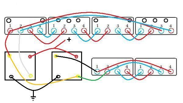
" the odd looking scheme I somewhat randomly posted back on page 7 "
____ Of-course I've seen those rather quite-nicely well-drawn pic.schemes you've posted, but they were-not complete enough (all on their own) to properly orient me so as to realize exactly which lead-ends go-to which coil-winding -(inner or outer), of each of the 2-pairs of power-coils. _ Cuz as I recall, you had indicated that the lead-ends (of each of the dual-windings) aren't all always consistently located as would be logically expected.
__ I've modified your posted-scheme so as to help explain what I mean. _ The modified version of your scheme-drawing includes some of the before-missing lead-end connections actually shown arranged & circuited as might be most-orderly expected. _ However, there's been some disconcerting confusion concerning the (actually varied) location-points of some lead-ends not always being consistently arranged the same on every power-coil, as would normally be expected otherwise. _ So my posted-drawing (as I happen to have it), will likely indicate some lead-end connections as actually incorrectly-connected (to the wrong circuits).
__ For your otherwise well drawn schemes to be properly comprehended, this raised-issue ought-to be elaborated.
____ Of-course your related-stuff concerning the magnets is of interest as well,, but since this-thread is already getting too-long, it wouldn't be very suitable to further extend it with still another off-shoot that may also add enough additional posts to make it worth being in a thread of it's own.
(NEXT, from Bill's last-post on the previous-page)...
" When I saw you were using 24ga my first reaction was that it was too extreme
(being roughly only half the cross sectional diameter from the stock wire) and the resistance would be too high. "
____ The thinner gauged wire was deemed necessary in order to fit a substantially longer length of winding onto the bobbin,, and the resulting increased resistance was not a concern because the 'prime-winding' was only meant to be matched-up with just a relatively high-resistance (lights off) system-load. _ So in THAT case, the thinner-wire (along-with it's increased resistance) would-not matter, (so long as the resistance of the ign.system is-not lower than that of the prime-winding [which is ONLY just two power-coils] ).
__ That's pretty-much along the same resistance-situation as connecting all 6-pairs of stock power-windings together, ALL in series, (thusly near 89ft of #20-gauge),, as those who've simply done-so (with their 6-pole w-c.alt), have discovered works quite well enough (so long as their chosen 12v.headlight doesn't demand too much current).
__ Another significant consideration is that if the thin gauged wire is wound as a 'double-winding', then such a power-winding can be TWICE the length of the 'equivalent' wire-gauge (as a single-winding) ! _ For example, a 'double-winding' of two 30ft.lengths (60ft.total) of 24-gauge wire equals only .38-ohms,, while the equivalent amp.current-carrying wire -(gauge-21), can only be just 30ft.long in total-length, in order to have that same .38-ohms !
In other-words, the three-gauge thinner double-winding can have the SAME resistance and the SAME current-flow capability, yet also be TWICE as long (to cut twice as much lines of flux) !!
" Now, with the two wires put together being pretty close/equivalent in cross section to the stock wire, "
____ A parallel-pair of gauge-#23 can equally conduct the same-amount of current as the stock #20-gauge, as the combined cross-section area of the pair of #23-gauge is equal to that of the stock wire-gauge !
" what we'd be testing for there becomes a side track and back to being more about resistance and parallel stuff
than what was Bob's original plan here (for the increased number of turns achieving better low rpm performance). "
____ I'm afraid I don't really follow exactly whatever the intended-jest may've actually been meant to be, but I don't see how adopting the parallel-pair of windings (in place of a single-winding) would become a side-track diversion from the MAIN-goal of increasing charging-system voltage at low-RPM... Because for the SAME-amount of resulted-resistance, the parallel-pair 'cuts' TWICE as much lines of flux ! _ And that means twice the amount of created-tension and potentially DOUBLE the produced-power (compared to the equivalent single-winding, with all-ELSE the same).
__ The original-plan was to hopefully attain a doubled number of loop-turns with an acceptable resulted amount of total-resistance (for the power-coil pair of the prime-winding).
But Bruce managed to far exceed that expected hope, (which was a GOOD-thing),, but along-with all the additional loop-turns, came excessive-resistance as well, (which is NOT a good-thing).
However, Bill came-up with the idea of double-windings, which conveniently cuts that excessive-resistance by 75%,, so therefore all those 10-layers of loop-turns can be retained without any-need for reducing the total-length of the power-winding !
__ So the bottom-line is that the parallel/double-winding is-not really a "side track", as it actually allows fully-maximized coil-windings without the inherent downside, (which is like having your cake AND eating it too, frosting & all !), since the total winding-length is doubled without the resulted resistance being any higher than that of the stock-gauge (that's a single-winding only half as long) ! _ So with the 'double-winding', we DO achieve TWICE the number of loop-turns with no resistance-cost/penalty, (which is pretty-much twice-the-bang,for-the-buck !).
" Is the distance of the additional wire from the core/post going to skew the results? "
____ The stator-core helps to intensify the strength of the magnetic flux-fields, and-so it's indeed fairly likely that the core's effect is actually somewhat reduced as the winding-loops get spaced further-away. _ However Bruce hasn't wound-outward far enough for that loss to become a concern,, and besides, the outermost winding-loops still get directly-bathed the same amount, from the rotor-magnets (even if not also indirectly by the core).
Enlightening-Cheers,
D.Bob
Troubleshooting Alternator Wiring
Moderator: ajleone
-
DewCatTea-Bob
- Posts: 2897
- Joined: Sun Nov 01, 2009 10:53 am
- Location: Near SE side of Lake Michigan
Possible Ultimate-parallel Coil-winding Arrangement
You do not have the required permissions to view the files attached to this post.
PLEASE NOTE... If this-post is not-yet signed-off with '-Bob', then I'm still in the process of completing it,, and if not also included with 'DCT' near bottom as well, then I may edit this post's wording at a later time. - Dct.Bob
-
ecurbruce
- Posts: 317
- Joined: Fri Apr 01, 2011 12:43 am
- Location: Hurricane mills TN
Re: Troubleshooting Alternator Wiring
Bob says" a std.brake-light ought-to consume around 15-watts, yet yours seems to only be near just 4-watts. "
That brake light had better be mizerly, it's LED-(1157 style bulb)! Would you expect a LED brake light bulb to consume something close to 4 watts, because if so, I'm getting current readings somewhere close to correct...???
Bob says;"__ Was your ".242" reading with the engine running (and charging-system taken off-line) ? "
That reading is with ignition on, engine not running. It compares with the reading of the ignition system of 0.138 amps with ignition on, engine not running.
Bruce.
-
wcorey
- Posts: 323
- Joined: Sun Jan 31, 2010 1:50 am
- Location: MA USA
Re: Troubleshooting Alternator Wiring
However, there's been some confusion concerning the actually varied location-points of the lead-ends not always being the same (as would normally be expected),, so the drawing (as I happen to have it), may possibly show some of the lead-end connections incorrectly-connected, to the wrong circuits.
__ For Bill's otherwise well drawn schemes to be properly comprehended, this raised-issue ought-to be elaborated.
I had been working on adding something to depict the windings (and direction of them) but was never satisfied with the results
so never got around to using any of them. In the old thread I has assumed we were all familiar enough with how things were
routed that there didn't seem to be an immediate need for it anyway.
It was all just work-in-progress at the time and nothing was 'finalized' as I naively though it would eventually be.
The physical arrangement of the wires coming out of the stock coils/bobbins is fairly consistent for
purposes of graphic rendition and with only one exception they all use the same basic order,
but just exit through different various holes.
The exception is the first large coil where the phasing is reversed from the other large one,
which is reflected in most of my drawings with the red/blue points being reversed.
That causes that particular parallel-from-hell drawing to have one error as the first 'block'
should have the connections reversed from all the others.
I had already noticed it but didn't bother with a correction because it still conveys the concept either way.
(one other that could possibly be considered an exception is the last coil where the last two 'grounded' wires exit through the same hole)
In both types of drawings I was/am using, there are two colors for the connections, red and blue.
Each color represents both a single continuous winding through the stator and also through the individual coils/bobbins (which have
their wires exiting in a staggered pattern, as do the drawings).
I don't think I ever was able to determine which were the actual inner/outer windings but only the phasing relative to each other.

This is a previously 'unpublished' alternate version that shows the the coils (and attempts to show phasing)
as well as correct routing on the first 'block'.

-
wcorey
- Posts: 323
- Joined: Sun Jan 31, 2010 1:50 am
- Location: MA USA
Re: Troubleshooting Alternator Wiring
For an interesting puzzle, take a stab at figuring out the significance of the 'gold' wire/connection in this scheme.
It may lead to some understanding of the as yet inexplicable difference in outputs between the mosfet r/r and 'standard' ones.
Bruce should have particular interest at this time as it's very related to what's going on in this thread, both the beginning and present.
And I know it's always niggled at Bob, from way back...
For the pertinent details I'll only point to the the very end of the old thread, it's the very last thing I had ended with there.
viewtopic.php?f=3&t=556&hilit=alternator+modifications&start=350
-
ecurbruce
- Posts: 317
- Joined: Fri Apr 01, 2011 12:43 am
- Location: Hurricane mills TN
Re: Troubleshooting Alternator Wiring
Bill says;"For an interesting puzzle, take a stab at figuring out the significance of the 'gold' wire/connection in this scheme."
Bill, do you know the answer to your question?
My uneducated guess is that it is bridging the two rec's and cutting the impedance in half, (as is done on an audio amplifier)???
Bruce
Bill, do you know the answer to your question?
My uneducated guess is that it is bridging the two rec's and cutting the impedance in half, (as is done on an audio amplifier)???
Bruce
-
wcorey
- Posts: 323
- Joined: Sun Jan 31, 2010 1:50 am
- Location: MA USA
Re: Troubleshooting Alternator Wiring
Bill, do you know the answer to your question?
No, I only know what I wrote about it in the link, basically that it has more output with that connection than without.
Not sure why/if it would reduce impedance but that could be an explanation if it indeed does.
-
DewCatTea-Bob
- Posts: 2897
- Joined: Sun Nov 01, 2009 10:53 am
- Location: Near SE side of Lake Michigan
Current-demand by Various Loads
[quote= ecurbruce ...
" That brake light had better be mizerly, it's LED-(1157 style bulb)! Would you expect a LED brake light bulb to consume something close to 4 watts,"
____ I've been under the impression that such equivalent LED.bulbs consume VASTLY-less power,, and-so while a std.bulb's brake-light circuit consumes 15 to 25-watts, I would've expected an equivalent LED.version to consume under 3-watts.
So since yours is under 4-watts, I assume that that's probably in fair-order.
" That reading is with ignition on, engine not running. It compares with the reading of the ignition system of 0.138 amps with ignition on, engine not running. "
____ I'm not surprised that your electronic-ign.circuitry consumes well under 1-amp without the engine running, but I'd expect it to draw considerably more current when it's actually producing ign.sparks.
__ If you still had a stock points-type ignition-system,, then the task of determining it's max.current-demand would be as simple as measuring the amperage-draw with the ign.points kept closed, (without the engine running).
____ In case you haven't yet noticed, I've finally gotten-around to responding to Bill's last-post placed on the previous-page. _ And to keep it better arranged in chronological-order, I've included that latest-response along-with my earlier response-post to Bill's previous/prior-post to that one, as well, (as seen within my prior-post on this-page).
__ So after you've digested all that, I then look forward to answering any spawned questions/concerns that may arise for you (or anyone-else) afterwords.
Hopeful-Cheers,
-Bob
PLEASE NOTE... If this-post is not-yet signed-off with '-Bob', then I'm still in the process of completing it,, and if not also included with 'DCT' near bottom as well, then I may edit this post's wording at a later time. - Dct.Bob
-
wcorey
- Posts: 323
- Joined: Sun Jan 31, 2010 1:50 am
- Location: MA USA
Re: Troubleshooting Alternator Wiring
" what we'd be testing for there becomes a side track and back to being more about resistance and parallel stuff
than what was Bob's original plan here (for the increased number of turns achieving better low rpm performance). "
____ I'm afraid I don't really follow exactly whatever the intended-jest may've actually been meant to be, but I don't see how adopting the parallel-pair of windings (in place of a single-winding) would become a side-track diversion from the MAIN-goal of increasing charging-system voltage at low-RPM...
No jest intended.
I just though that adding the parallel winding into the mix might complicate things as far as interpreting what
results came from what, as we'd be testing both additional windings as well as the parallel ones at the same time.
So the bottom-line is that the parallel/double-winding is-not really a "side track", as it actually allows fully-maximized coil-windings without the inherent downside, (which is like having your cake AND eating it too, frosting & all !), since the total winding-length is doubled without the resulted resistance being any higher than that of the stock-gauge (that's a single-winding only half as long) ! _ So with the 'double-winding', we DO achieve TWICE the number of loop-turns with no resistance-cost/penalty, (which is pretty-much twice-the-bang,for-the-buck !).
I dunno, I'm still not sold on this, it's just too easy.
If putting two separate coils in parallel cuts the voltage in half (from what they'd be in series), then it seems like all we're doing
is is doubling the number of turns and then cutting whatever effect that would have in half by putting them in twin/parallel.
It seems to me that just as with a multi-stranded wire as opposed to single conductor wire, if the cross section area is the same,
they're effectively the same.
So why is this different?
-
DewCatTea-Bob
- Posts: 2897
- Joined: Sun Nov 01, 2009 10:53 am
- Location: Near SE side of Lake Michigan
Coil-winding Particulars
____ I appreciate your good-questions, Bill ! _ I've tackled them in shown-order, below.wcorey wrote:
No jest intended.
I just though that adding the parallel winding into the mix might complicate things as far as interpreting what
results came from what, as we'd be testing both additional windings as well as the parallel ones at the same time.
I dunno, I'm still not sold on this, it's just too easy.
If putting two separate coils in parallel cuts the voltage in half (from what they'd be in series), then it seems like all we're doing
is is doubling the number of turns and then cutting whatever effect that would have in half by putting them in twin/parallel.
It seems to me that just as with a multi-stranded wire as opposed to single conductor wire, if the cross section area is the same,
they're effectively the same.
So why is this different?
wcorey wrote:
" No jest intended.
I just though that adding the parallel winding into the mix might complicate things as far as interpreting what
results came from what, as we'd be testing both additional windings as well as the parallel ones at the same time. "
____ Okay, NOW I'm clear on where you were actually 'coming-from' -(meaning the 'jest' of your previously-posted & currently-presented wording). ...
____ The 'parallel-winding' AND the 'extended-winding' are both actually one & the-same power-winding ! _ Those two references are just different aspects for referring to the very-same winding. ...
The AMOUNT of power produced by a single-length (say 60ft) winding is-NOT changed by being wound rather as two half-lengths (2x30ft),, as the only difference that the half-length parallel-pair causes, is the same effect as-if the single full-length winding had somehow achieved well-reduced resistance (like super-cooled silver or some other future-exotic conductor), which merely-just lowers the resistance-point at which THE max.available-power could be achieved at.
__ For instance, IF the intended/test-load happened to have a resistance of as high as 4-ohms, THEN we would-not have as much need to keep the power-winding's resistance lowered so much below such a 4-ohm level,, cuz for optimum/max.power-transfer, it's BEST if the power-winding & the load both have the very-same amount of impedance/resistance, (regardless of whether that matched-level is rather low or rather high) !
So therefore, so long as such a 'match' occurs, (not only will there be no-difference in the amount of 'produced-power'), the 'available-power' will remain unchanged ! _ And-so only the 'test-load' would need to be properly adjusted in order to discover whatever THE max.available-power actually is !
__ Now on the other-hand,, the total-length of the winding, (whether a double-winding OR rather a simple single-winding), DOES actually affect the AMOUNT of produced-power !
So THAT-aspect will provide the ONLY true change/increase in 'produced-power' ! _ And how that power is measured & properly-determined, depends-on properly 'matching' the test-load's resistance to the power-winding's actual impedance.
And the test-load's optimum-resistance will simply accordingly-vary depending-on whether the power-winding happens to be a (higher resistance) single-winding or a (lower resistance) double-winding type. _ That's-ALL (there is to that) ! - (NO-differences in actual produced-power due-to just the TYPE of winding !).
__ So the bottom-line is that ONLY the total winding-length will make any difference in produced-power, since the 'test-load' will need to be varied-around in order to finally pin-down exactly-what the actual available-power can actually fully-be,, and thusly remove the power-winding's type totally out-of the picture !
(Now IF the test-load had to be FIXED at some particular resistance-value,, THEN the winding-type to be tested, would then indeed present just-cause for your brought-up concern !)
" I dunno, I'm still not sold on this, it's just too easy. "
____ I'm not sure of exactly-what you're actually in reference-to,, but would it help clear-up your related-concern if you imagine a simple-winding of a single loop-turn of gauge-#4 cutting invisibly-thin flux-lines, and then next imagine that same #4 thickness-size completely filled-up with gauge-#24 (which would amount to 103 separate wire-strands), ALL cutting the same flux-lines. ...
Well now of-course you must already realize that (insulation-coating aside), all those 103 individual thin-strands would equally conduct the SAME-amount of current and-with the same-amount of resistance as the single #4-loop, YET all those 103 insulated-strands would cut the flux-lines 103-times, (whereas the single FAT/#4-loop would only do-so just ONCE) !
Well then, it's in that same fashion that the parallel/double-winding would have the doubled-advantage of cutting flux-lines TWICE as many times (as an equivalent thicker-gauged single-winding) ! _ And it's the cutting-action which creates the tension that leads-to power-production.
__ (I know what question this should next lead-to, but I don't really want to get-into asking & answering my-own questions.)
" If putting two separate coils in parallel cuts the voltage in half (from what they'd be in series), then it seems like all we're doing
is is doubling the number of turns and then cutting whatever effect that would have in half by putting them in twin/parallel. "
____ I don't believe your question (as worded) makes proper-sense but, I think I know what you're meaning to get-at.
__ Firstly however,, you seem stuck thinking in terms of actual 'voltage', (as-if 'voltage' was already established). _ Why do you continue to think that any authentic 'voltage' is provided by ANY length of a coil-winding ? - (Even after your-OWN stator-winding test-work has established that real-voltage doesn't actually exist before becoming circuited !?)
__ There's actually NO real/authentic voltage to be cut-in-half in the first-place ! _ As 'voltage' is a refined & set-amount of tension, and a power-winding only offers merely-just raw/unrefined-tension (which builds-up regardless of whether arranged & compiled in series or parallel). _ Actual-voltage (from raw-tension) can't come into existence until AFTER a circuit FORMS the power/tension into some combination of current & voltage ! _ So only after that occurrence, can ya then cut voltage in-half or add voltages together.
__ I had expected that you had begun to grasp that concept those couple of years back, and would pretty-much understand it well enough by-NOW.
With alt.power-windings, we aren't dealing with any 'voltage', as voltage is something that ONLY adds just in 'series' (but NOT in 'parallel') !
RATHER, we're dealing with raw-tension,, and while it's true that the tension developed within a length of wire is also cut in-half when the length is cut in-half, the total-tension (unlike 'voltage'!) remains the SAME total-amount, no-mater whether arranged side-by-side in parallel or stacked in series !
In like-kind,, would you expect two people standing side-by-side on a weight-scale to weigh any higher by having one stand atop the other ? - (Of-course not !) _ Tension is the same way, it's just 'pressure' -(electrical-weight, of-sorts,, if ya will). _ And the TOTAL-amount of pressure/tension (no matter how it's arranged or orientated), is that which finally gets converted into whatever amount of voltage a connected-CIRCUIT happens to allow !!
" It seems to me that just as with a multi-stranded wire as opposed to single conductor wire, if the cross section area is the same,
they're effectively the same. "
____ Well yes, of-course indeed-so (in most-all respects, except for concern with insulation-medium) !
__ This aspect-concern which you've brought-up, is pretty-much the topic-issue that I expected should be next asked about after I gave my related-example of such a comparison.
In my (above)-offered comparison, I compared a single-loop of #4 solid-core wire against it's equivalent-number of #24 wire-strands... The #24-gauge was chosen because that's what Bruce has already worked with, and the #4-gauge was chosen because it's thickness is equal to the same height as the 5mm-height that Bruce had reached with the 10-layers of #24-wire.
" So why is this different? "
____ It seems as-if you're asking the same as why-not wind all the loop-turns (of even a single-type winding-length), without any insulation-coating between them !?
__ Anyhow, the answer to that-question must-be that the insulation-coating SEPARATING the conducting-mass effectively further combs the produced-tension to be more uniformed and-thus less likely to partially-cancel or be left inert as obstructive eddy-currents, and-therefore left with no-other choice but to combine & chain-up within the ONLY-pathway available -(the rather thinned wire-circuit),, would be my-own deductive-guess.
____ I wouldn't be too surprised to learn-of most MIT.professors also misusing the base-terminology of the term 'voltage', just as most everyone-else indeed DOES,, but the few who actually fully-understand that which distinguishes the definition of 'voltage' from other similar terms, would be the sorts of whom I-myself would find quite-interesting to hear THEIR-own explanation concerning the jest of your stated-question ! - (In other-words, if they're anyone who realizes exactly what 'voltage' actually IS,
THEN I'd be extra-interested to learn-of THEIR explanation to your intended-inquiry [about WHY there's any difference]!)
____ I've now got this entire post pretty-much all-done.
While I've edited a lot of all the wording, only that done in blue reflects substantial-change from before.
Done-Cheers,
DCT-Bob
You do not have the required permissions to view the files attached to this post.
PLEASE NOTE... If this-post is not-yet signed-off with '-Bob', then I'm still in the process of completing it,, and if not also included with 'DCT' near bottom as well, then I may edit this post's wording at a later time. - Dct.Bob
-
wcorey
- Posts: 323
- Joined: Sun Jan 31, 2010 1:50 am
- Location: MA USA
Re: Troubleshooting Alternator Wiring
<Edit>
Bob, you can ignore this if it's the first time you're reading this post...
Wasn't sure if I was addressing your full post or a partially done post at the time I was writing/submitting my post...
Now I go back and see you've of course added more, namely the part about total length, which throws a wrench into my response and whole train of thought on this.
I don't have time tonight to re-digest this and alter my post accordingly, so if you had already copy/pasted my now deleted response, give me some time before you respond to it or you'll be doing the same thing I just did.
Return to “Ducati Singles Main Discussions (& How to Join)”
Who is online
Users browsing this forum: No registered users and 99 guests