Bob says;"__ Can you measure the actual thickness of your chosen wire, to make-sure that it's a full .020" thick ? "
Indeed it is,, actually .0215
Quote;"
" What are the consequences of spinning two or more strands around the bobbin simultaneously "
____ I've leave that for Bruce to answer for us.
I can wind two wires, three would be like winding a may- pole (no-thanks)!
Do you want the windings paired side-by-side as they're wound, or do you want them piggy-back like one on top of the other as they're wound?
Choose a gauge and length of wire (which is to say - how full do you want these bobbins, like they were originally, or full to the top?)and I'll wind a pair for testing.
( that's a "slot-car" motor-cheater's wind)
If what you say is true, Bob, that will be a wind that's worth the trouble.
Bruce.
Troubleshooting Alternator Wiring
Moderator: ajleone
-
ecurbruce
- Posts: 317
- Joined: Fri Apr 01, 2011 12:43 am
- Location: Hurricane mills TN
-
ecurbruce
- Posts: 317
- Joined: Fri Apr 01, 2011 12:43 am
- Location: Hurricane mills TN
Re: Troubleshooting Alternator Wiring
Bob says;"____ Bruce, you need to measure the amount of current-draw that your ign.system consumes"
With ignition on...=0.138 amps
With ign. on, engine running...=0.9 to0.4 (digital meter jumps all over the place)
I do see the analog bar on my meter spiking way up though, with engine running.
Bruce.
With ignition on...=0.138 amps
With ign. on, engine running...=0.9 to0.4 (digital meter jumps all over the place)
I do see the analog bar on my meter spiking way up though, with engine running.
Bruce.
-
DewCatTea-Bob
- Posts: 2897
- Joined: Sun Nov 01, 2009 10:53 am
- Location: Near SE side of Lake Michigan
Testing Load-system's Current-consumption
[quote= ecurbruce ...
" With ignition on...=0.138 amps "
____ I'm sure that your ENTIRE ign.system consumes way-more than that small amount !
Your under two-tenths of a single amp, must be merely the amount consumed by just your electronic-ign.box/circuit.
Between what circuit-points did you insert your ammeter ?
" With ign. on, engine running...=0.9 to0.4 "
____ Is that with the charging-system left connected-up ?
____ Here's how to definitely determine the amount of amperage that your load-system draws...
First with your battery being fully charged-up, and charging-system taken off-line,, insert amp-meter between the battery's ground-wire & ground. _ Then take note of ammeter-reading both with engine running and not-running (but with ignition turned-on).
__ While you're there, you ought-to take readings with your headlight-circuits turned-on, as well.
\
Hopeful-Cheers,
-Bob
PLEASE NOTE... If this-post is not-yet signed-off with '-Bob', then I'm still in the process of completing it,, and if not also included with 'DCT' near bottom as well, then I may edit this post's wording at a later time. - Dct.Bob
-
DewCatTea-Bob
- Posts: 2897
- Joined: Sun Nov 01, 2009 10:53 am
- Location: Near SE side of Lake Michigan
Winding-length... Moderate or Extra-extravagant ?
[quote= ecurbruce ...
" Indeed it is,, actually .0215 "
____ Okay then, I guess you must've fit ALL that extra winding-length by just your-own method alone.
__ BTW, the data-sheet stated ".0201" for gauge-#24,, perhaps due-to the insulation-coating not being included ?
" I can wind two wires, "
____ I was in the process of the "rethink" and wondering how long you could possibly extend thicker-gauged windings (like #18 & #22), when I next discovered Bill's possible solution to the resistance build-up issue with such extended windings (as you were able to accomplish).
So my rethink-thought was then put on-hold until we could get your answer on whether you could possibly wind 'double-windings'.
__ Now that you've replied positively, it looks very-much like we will be able to achieve the 'ULTIMATE' 6-pole alt.stator, after all !
" Do you want the windings paired side-by-side as they're wound, or do you want them piggy-back like one on top of the other as they're wound? "
____ Fortunately, the easier to accomplish side-by-side method, is preferred for the 'DOUBLE-winding' , which we now wish to employ !
Because in order for it to work PROPERLY & best, we then need both wires to be EXACTLY 'matched' ! _ And 'side-by-side' should make-sure that both wires are wound the exact same length, (whereas the 'piggy-back' winding-method would lead-to the upper/outer wire becoming LONGER !).
" Choose a gauge and length of wire "
____ I think that should be left up-to YOU, Bruce.
Here's the reasoning... The 'prime-winding' shouldn't really need to produce a whole lot of power, since it's not expected to be required to power a very demanding load.
In which case, a SINGLE 8-layer winding of gauge-#23 ought-to be the final-choice, (however still depending-on how much juice your ign.system draws).
But on the other-hand, if you prefer to go-for 'THE-MAX',, then in THAT case, I'd suggest a 'double-winding' of gauge-#25 or #26 that's (hopefully) 12-layers high.
" how full do you want these bobbins, like they were originally, or full to the top? "
____ Again, THAT should be up-to YOU !
The more loop-turns of wire that you can possibly fit around the bobbins, the greater then will be the power-output !
Before, with just SINGLE-wire windings, resistance build-up would then be at odds against most efficient power-transfer out-TO the intended load,, but now with 'DOUBLE-wire' windings, the only remaining concern is making-sure that the coil-winding is-not too-bulging/fat to fit in the space above the surface of the stator-plate.
" If what you say is true, Bob, that will be a wind that's worth the trouble. "
____ Not-sure what you're referring-to exactly,, but in regards-to total-resistance, it's indeed a fact that there's a 4-times difference depending-on whether in 'series' or 'parallel' !
Hopeful-Cheers,
-Bob
" Indeed it is,, actually .0215 "
____ Okay then, I guess you must've fit ALL that extra winding-length by just your-own method alone.
__ BTW, the data-sheet stated ".0201" for gauge-#24,, perhaps due-to the insulation-coating not being included ?
wcorey wrote: What are the consequences of spinning two or more strands around the bobbin simultaneously
" I can wind two wires, "
____ I was in the process of the "rethink" and wondering how long you could possibly extend thicker-gauged windings (like #18 & #22), when I next discovered Bill's possible solution to the resistance build-up issue with such extended windings (as you were able to accomplish).
So my rethink-thought was then put on-hold until we could get your answer on whether you could possibly wind 'double-windings'.
__ Now that you've replied positively, it looks very-much like we will be able to achieve the 'ULTIMATE' 6-pole alt.stator, after all !
" Do you want the windings paired side-by-side as they're wound, or do you want them piggy-back like one on top of the other as they're wound? "
____ Fortunately, the easier to accomplish side-by-side method, is preferred for the 'DOUBLE-winding' , which we now wish to employ !
Because in order for it to work PROPERLY & best, we then need both wires to be EXACTLY 'matched' ! _ And 'side-by-side' should make-sure that both wires are wound the exact same length, (whereas the 'piggy-back' winding-method would lead-to the upper/outer wire becoming LONGER !).
" Choose a gauge and length of wire "
____ I think that should be left up-to YOU, Bruce.
Here's the reasoning... The 'prime-winding' shouldn't really need to produce a whole lot of power, since it's not expected to be required to power a very demanding load.
In which case, a SINGLE 8-layer winding of gauge-#23 ought-to be the final-choice, (however still depending-on how much juice your ign.system draws).
But on the other-hand, if you prefer to go-for 'THE-MAX',, then in THAT case, I'd suggest a 'double-winding' of gauge-#25 or #26 that's (hopefully) 12-layers high.
" how full do you want these bobbins, like they were originally, or full to the top? "
____ Again, THAT should be up-to YOU !
The more loop-turns of wire that you can possibly fit around the bobbins, the greater then will be the power-output !
Before, with just SINGLE-wire windings, resistance build-up would then be at odds against most efficient power-transfer out-TO the intended load,, but now with 'DOUBLE-wire' windings, the only remaining concern is making-sure that the coil-winding is-not too-bulging/fat to fit in the space above the surface of the stator-plate.
" If what you say is true, Bob, that will be a wind that's worth the trouble. "
____ Not-sure what you're referring-to exactly,, but in regards-to total-resistance, it's indeed a fact that there's a 4-times difference depending-on whether in 'series' or 'parallel' !
Hopeful-Cheers,
-Bob
PLEASE NOTE... If this-post is not-yet signed-off with '-Bob', then I'm still in the process of completing it,, and if not also included with 'DCT' near bottom as well, then I may edit this post's wording at a later time. - Dct.Bob
-
wcorey
- Posts: 323
- Joined: Sun Jan 31, 2010 1:50 am
- Location: MA USA
Re: Troubleshooting Alternator Wiring
" it seems in one of those
past schemes I must have wired the stock coils to have similar effect but can't recall. "
____ I only recall of you unchaining each power-coil's dual-windings (from their two individual stock stator-circuits), and then reconnecting them rather to each-other in series-fashion, (but never together in parallel).
There were quite a few tests/schemes I had done back then that went 'unpublished', simply due to lack of time in many instances.
It of course has occurred to me well after the fact what I had been up to, that lead to this particular concept/scheme.
Toward the end of the past project, I had worked out a parallel-from-hell scheme (you'd think of it more as an imbalance-mismatch-from-hell)
that more or less maximized just how parallel the stator circuit could possibly get.
But by then, reducing the winding resistance had become less of an issue so I never bothered to actually implement it.
I was also concerned that the imbalance issue that appeared to me to be minor on the 'e' scheme and single rec 3-sec scheme
would likely become much more aggravated by this one.
If I get motivated enough, I just might try it though.
To exemplify what a short memory I sometimes exhibit, the odd looking scheme I somewhat randomly posted back on page 7 is it...
Quite another thing that I had planned but never got around to was to make a rotor using
the rare earth magnets from a more modern rotor. Gutting a stock 4 pole rotor and
cutting out the id a bit looks like it would get me sufficient space to work with.
Not only is the magnetic force likely to be double or more over stock but I could also maybe fit 12 magnets in there.
I had been searching for a newer type rotor that had both the right size/number of magnets and the right internal diameter
but only found one or the other.
In my estimation this alone would have yielded sufficient power with even an unmodified 4 coil stator.
Of course then I might as well go on to convert the stator to 3 phase again and try to squeeze in 16 magnets.
350 watts, anyone...?
-
ecurbruce
- Posts: 317
- Joined: Fri Apr 01, 2011 12:43 am
- Location: Hurricane mills TN
Re: Troubleshooting Alternator Wiring
Bill , it looks like the maximized parallel scheme you show is what we would be doing with the double wound spools. We will be right back to two coils per spool. The advantage I can see to the double wound version is that both coils would be in the same close proximity to the permanent magnet field, and I can get more wind-turns on each bobbin than Ducati used.
I am going to be out of pocket for the next ten days, don't think I'm jumping ship, I'll be keeping up in the background. When I return, I plan to do some winding, if you do get motivated to configure and test that maximized parallel system in the mean time, we'll compare it to the double wound version when I can get it done, what do you think?
Meanwhile, Bill do you have an opinion on wire size for the double wound coils?
Bob, this is the ignition system that I'm using,
It's fed directly from the ignition switch at S114. I don't use G112, and ground through S113. There is only one feed for the coil and module. I disconnected that feed from the ignition switch, and attached the amp meter in line there.
More testing to come
Bruce.
I am going to be out of pocket for the next ten days, don't think I'm jumping ship, I'll be keeping up in the background. When I return, I plan to do some winding, if you do get motivated to configure and test that maximized parallel system in the mean time, we'll compare it to the double wound version when I can get it done, what do you think?
Meanwhile, Bill do you have an opinion on wire size for the double wound coils?
Bob wrote: ____ I'm sure that your ENTIRE ign.system consumes way-more than that small amount !
Your under two-tenths of a single amp, must be merely the amount consumed by just your electronic-ign.box/circuit.
Between what circuit-points did you insert your ammeter ?
Bob, this is the ignition system that I'm using,
It's fed directly from the ignition switch at S114. I don't use G112, and ground through S113. There is only one feed for the coil and module. I disconnected that feed from the ignition switch, and attached the amp meter in line there.
More testing to come
Bruce.
You do not have the required permissions to view the files attached to this post.
Last edited by ecurbruce on Sat Aug 31, 2013 1:27 pm, edited 1 time in total.
-
DewCatTea-Bob
- Posts: 2897
- Joined: Sun Nov 01, 2009 10:53 am
- Location: Near SE side of Lake Michigan
Winding-parameter Considerations
____ Just as I was going to begin a response to Bill's post, Bruce's (more pertinent) post popped-up, so now I'm led to post under IT instead.
[quote= ecurbruce ...
" Bill , it looks like the maximized parallel scheme you show is what we would be doing with the double wound spools. "
____ No, not-quite THAT-extensive,, as the large/small power-coil pairs (within each of the three sections) will still be rather connected in series to each-other !
__ Bill's ultimate-parallel scheme would have ALL-12 individual windings all connected-together in parallel !
" We will be right back to two coils per spool. "
____ Yes but, I wouldn't say "right back",, cuz the intended 'double-wound' coil-pairs will be exactly the same length as each-other (instead of the outer-windings being slightly longer than the inner-ones [as with Ducati's 'dual-windings') !
" The advantage I can see to the double wound version is that both coils would be in the same close proximity to the permanent magnet field, "
____ While that may be a slight viable consideration, (since the original dual-winding's loop-sets don't cut the very-same flux-lines),, the REAL 'advantage' of the 'DOUBLE-winding', is that it's resulting winding 'pair' is naturally 'MATCHED' , (thus no interaction losses) !
" if you do get motivated to configure and test that maximized parallel system "
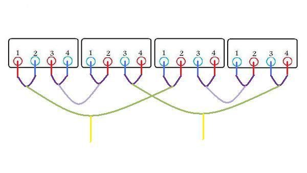
____ Even though having divided-up the set of 6 power-coils into 3-pairs and connecting-up the resulted 3 series-sections in parallel with each-other, has already quite well proven the case,, showing that the resulted output-voltage of all 12-windings connected in parallel is STILL just as high as if all were connected in 'series',
would even more-so prove-the-point that alternator-windings (unlike battery-cells) do-NOT produce their-own 'voltage' !! - (Since 'voltage' can ONLY be 'added' in 'SERIES' !) -
In other-words, IF each individual stator-winding actually produced any pre-established/true 'voltage' , THEN that ultimate parallel-arrangement would only provide just 1/12th as much voltage as all twelve coil-windings arranged in series ! _ BUT that established series vs. parallel voltage-law is-NOT followed by alt.power-windings, (as is commonly ASSUMED) !
That seemingly rule-breaking revelation, is evidence for why the commonly-conceived 6+6=12 concept, (as promoted in the mag.article), is INCORRECT !
" this is the ignition system that I'm using,
It's fed directly from the ignition switch at S114. I don't use G112, and ground through S113. There is only one feed for the coil and module. I disconnected that feed from the ignition switch, and attached the amp meter in line there. "
____ Well it SEEMS that THAT should've done the job of measuring the current drawn by the ign.system,,
HOWEVER, I can hardly believe that it only consumes such a small amount !
__ Anyhow, we actually need to know how much current your entire load-system consumes, both with lights ON & OFF !
So-then you need to do the test as I've already instructed, (by measuring all current LEAVING the battery to ground !).
" More testing to come "
____ First make-sure that your battery is fully charged-up, and that the output -(red/center-terminal) of your R-R.box is disconnected.
Hopeful-Cheers,
DCT-Bob
[quote= ecurbruce ...
" Bill , it looks like the maximized parallel scheme you show is what we would be doing with the double wound spools. "
____ No, not-quite THAT-extensive,, as the large/small power-coil pairs (within each of the three sections) will still be rather connected in series to each-other !
__ Bill's ultimate-parallel scheme would have ALL-12 individual windings all connected-together in parallel !
" We will be right back to two coils per spool. "
____ Yes but, I wouldn't say "right back",, cuz the intended 'double-wound' coil-pairs will be exactly the same length as each-other (instead of the outer-windings being slightly longer than the inner-ones [as with Ducati's 'dual-windings') !
" The advantage I can see to the double wound version is that both coils would be in the same close proximity to the permanent magnet field, "
____ While that may be a slight viable consideration, (since the original dual-winding's loop-sets don't cut the very-same flux-lines),, the REAL 'advantage' of the 'DOUBLE-winding', is that it's resulting winding 'pair' is naturally 'MATCHED' , (thus no interaction losses) !
" if you do get motivated to configure and test that maximized parallel system "
____ Even though having divided-up the set of 6 power-coils into 3-pairs and connecting-up the resulted 3 series-sections in parallel with each-other, has already quite well proven the case,, showing that the resulted output-voltage of all 12-windings connected in parallel is STILL just as high as if all were connected in 'series',
would even more-so prove-the-point that alternator-windings (unlike battery-cells) do-NOT produce their-own 'voltage' !! - (Since 'voltage' can ONLY be 'added' in 'SERIES' !) -
In other-words, IF each individual stator-winding actually produced any pre-established/true 'voltage' , THEN that ultimate parallel-arrangement would only provide just 1/12th as much voltage as all twelve coil-windings arranged in series ! _ BUT that established series vs. parallel voltage-law is-NOT followed by alt.power-windings, (as is commonly ASSUMED) !
That seemingly rule-breaking revelation, is evidence for why the commonly-conceived 6+6=12 concept, (as promoted in the mag.article), is INCORRECT !
" this is the ignition system that I'm using,
It's fed directly from the ignition switch at S114. I don't use G112, and ground through S113. There is only one feed for the coil and module. I disconnected that feed from the ignition switch, and attached the amp meter in line there. "
____ Well it SEEMS that THAT should've done the job of measuring the current drawn by the ign.system,,
HOWEVER, I can hardly believe that it only consumes such a small amount !
__ Anyhow, we actually need to know how much current your entire load-system consumes, both with lights ON & OFF !
So-then you need to do the test as I've already instructed, (by measuring all current LEAVING the battery to ground !).
" More testing to come "
____ First make-sure that your battery is fully charged-up, and that the output -(red/center-terminal) of your R-R.box is disconnected.
Hopeful-Cheers,
DCT-Bob
PLEASE NOTE... If this-post is not-yet signed-off with '-Bob', then I'm still in the process of completing it,, and if not also included with 'DCT' near bottom as well, then I may edit this post's wording at a later time. - Dct.Bob
-
ecurbruce
- Posts: 317
- Joined: Fri Apr 01, 2011 12:43 am
- Location: Hurricane mills TN
Re: Troubleshooting Alternator Wiring
Bob wrote:__ Anyhow, we actually need to know how much current your entire load-system consumes, both with lights ON & OFF !
So-then you need to do the test as I've already instructed, (by measuring all current LEAVING the battery to ground !).
Some inconclusive testing, because I've not had much extra time right now to set up tests, and the battery is only at 11.6 volts. I'll get back to this at a later date, with a fully charged battery.
With meter between negative cable and neg. post of battery, ignition switch on,=.242 amps. Add pressing brake pedal,=.28 amps, so the measuring process is working.
Didn't even try headlamp with battery low, (I won't run battery charger current through my meter,)
So I'll get back to this later, and get more complete results. Sorry about the so hit & miss concerning this testing.
((Bob, or Jim, I have an unrelated side note, I'm having difficulty getting photos onto my posts. In that last post I would have preferred that schematic at the end of my post, and being positioned at the beginning is kind of confusing when just after the photo you start reading an unrelated subject.
I added that photo last thing after typing text, but it comes out on top instead of at the end... What to do???))
Bruce
-
wcorey
- Posts: 323
- Joined: Sun Jan 31, 2010 1:50 am
- Location: MA USA
Re: Troubleshooting Alternator Wiring
Meanwhile, Bill do you have an opinion on wire size for the double wound coils?
Bottom line on that is Bob is much more technically qualified to make those determinations.
When I saw you were using 24ga my first reaction was that it was too extreme
(being roughly only half the cross sectional diameter from the stock wire) and the resistance would be too high.
But since we're just testing a theory it likely wouldn't matter anyway as whatever data we get can probably be extrapolated up or down.
Now, with the two wires put together being pretty close/equivalent in cross section to the stock wire,
what we'd be testing for there becomes a side track and back to being more about resistance and parallel stuff
than what was Bob's original plan here (for the increased number of turns achieving better low rpm performance).
So if you want to be efficient and at the same time test what the effect of the increased number of wraps around the bobbin is,
then one gauge thinner wire may be in order.
But then again you're already getting more overall wire on the bobbins so that may be enough
to test that, though it might be hard to differentiate what results are from what change.
Is the distance of the additional wire from the core/post going to skew the results?
Again I would defer to Bob to know what's best.
Then still again, since you have a set already single wound and are about to take a break from it, maybe just send them and I can likely test and have them
back to you by the time you're ready for a rewind.
Many options, pick one...
I'm curious... is your Dad still following any of this? Tell him I said "Hi"...
-
DewCatTea-Bob
- Posts: 2897
- Joined: Sun Nov 01, 2009 10:53 am
- Location: Near SE side of Lake Michigan
Conservative Power-consumptions
[quote= ecurbruce ...
" With meter between negative cable and neg. post of battery, ignition switch on,=.242 amps. Add pressing brake pedal,=.28 amps, so the measuring process is working. "
____ I really don't know what to expect exactly from YOUR ign.system, but a std.brake-light ought-to consume at-least 15-watts, yet yours seems to only be near just 4-watts.
__ Now if your headlight is also so extra miserly, then your alternator is already going to make way-TOO-MUCH power !
__ Was your ".242" reading with the engine running (and charging-system taken off-line) ?
" I'm having difficulty getting photos onto my posts. In that last post I would have preferred that schematic at the end of my post,
I added that photo last thing after typing text, but it comes out on top instead of at the end... "
____ I really don't have any explanation as to how you managed to do that...
I just tried it myself, and the entered pic became placed in the regular position at the bottom of your post, as usually is the norm.
Of-course, you may remove whichever pic you wish to.
Hopeful-Cheers,
-Bob
PLEASE NOTE... If this-post is not-yet signed-off with '-Bob', then I'm still in the process of completing it,, and if not also included with 'DCT' near bottom as well, then I may edit this post's wording at a later time. - Dct.Bob
Return to “Ducati Singles Main Discussions (& How to Join)”
Who is online
Users browsing this forum: No registered users and 99 guests