[quote= ecurbruce ...
" I'm kind-of leaning towards "Plan A", "
____ THAT plan will lead to more complex workings.
" Gauges of solid magnet wire available at the moment; "
18,22,25,26,27,28,29,30,31,32,33,34,36,37,38,40 "
____ I'm fairly-sure that nothing thinner than #23 will be needed, and quite-sure that nothing thinner than #25 could possibly be used, (and those guesses are spotted outside of the expected ball-field). _ I'd need to know the measured-diameters (determined by a micrometer), in order to do the related math.
If the range of available gauge-sizes were rather within the range of 15;16;17;18;19;20;21;22;23;24, then I'd certainly be quite confident of finding the exact size(s) actually needed !
" I guess for the sake of keeping our test results fair, we should stay with copper anyway, what do you think? "
____ I understand that there are 'grades' of copper available, and the purest would be an acceptable alternative to silver. _ I don't see any reason to be "fair" by using whatever grade that Ducati had determined would be adequately balanced against their economic concerns.
__ The reason that silver-wire would be preferred, is that it's a fair-step closer towards what could be obtained with 'superconductive' wire,, let me explain...
When Bill would measure the 'current' through the 'circuit' of one of his test-circuit setups, where-then the test-load's resistance was (closely) 'matched' to the impedance of the tested power-coil arrangement,, he was then not-only measuring the current flowing-through the load itself, but of-course also the very-same current flowing-through the alternator-windings as-well !
And when he measured the 'voltage',, that-voltage was not-only dropped-across the intended 'load', but ALSO that dropped-across the alt.windings AS-WELL !
That means that at-BEST,, only one-HALF of all the produced-power created by the alternator actually gets spent-on the load-system, whilst the other-half is fully WASTED (as heat-production) by the alt.winding itself !
And-also, if the impedance of the alt.winding ever exceeds the resistance of the load-system, THEN the majority of the produced-power becomes wasted by the alt.stator-itself, thus-then leaving less of the produced-power to be consumable by the intended-load !
__ That's obviously a poor-situation,, but with the use of 'superconductive-wire' (which has ZER0-resistance !), then ALL/100% of the produced-power would be left-over for JUST the load-system, alone !
That means that by so greatly reducing the waste of power dissipated by the alt.stator-winding,, that factor alone/all on it's own, would lead-to near DOUBLING the available-power left usable for consumption by the intended-load !
Now while we certainly don't have access to such fabulous/futuristic-wire,, silver-wire does take us a fair step towards that ultimate-efficiency, (albeit a relatively small step).
__ So if you could obtain it, then I'd suggest making-use of 'silver-wire' for the intended 'prime-winding'.
____ I had rather over-optimistically suggested the intention of creating an "ultimate" 6-pole alt.stator,, but unless we use silver-wire THROUGHOUT the entire stator, AND connect-up ALL-six power-coils in 'parallel',, it really wouldn't actually be fair to promote the intended project-stator as the 'ULTIMATE' alt.stator !
So I guess we should rather refer to it as something more-so on-par, as we rather intend to merely conceive a more down-to-earth stator-version.
" I meant to measure the original winding wire "
____ My GUESS is that it's about 16-gauge, (as would seem to-be reasonable for a 6v.system).
____ Bruce's present stator-winding's total-resistance is set at .225-ohms -(.15-ohms average, per power-coil), (which doesn't take into account the added impedance as RPM/frequency increases). _ While the project-stator, (if wound with the SAME stock-wire & number of turns), would have a total-resistance of just .1-ohm,, which is an improvement of 56% closer towards complete power-transfer efficiency (not counting the expected added impedance-factor).
So we know that the project-stator will already provide more 'available-power' (than that which Bruce now has), by just having a reduced total-resistance.
__ However I will obviously have to do some math to make-sure that the chosen wire-gauge/length doesn't raise the total-resistance back-up too much.
It will also be fairly-important to learn what the absolute-minimum total-resistance of Bruce's intended load-system will be, so that the project-stator's resistance doesn't ever end-up becoming higher than that of the load-system's.
So we'd at-least need to know the current-draw amperage consumed by his headlight & ign.system ! _ (Loads like brake-light & horn, [though they do consume significant power-juice], are-not of any real concern [with systems which employ a battery] !)
____So what are your related thoughts NOW, Bruce ?
Enlightening-Cheers,
-Bob
Troubleshooting Alternator Wiring
Moderator: ajleone
-
DewCatTea-Bob
- Posts: 2897
- Joined: Sun Nov 01, 2009 10:53 am
- Location: Near SE side of Lake Michigan
Preferred-wire for Alt.stator-wingings
PLEASE NOTE... If this-post is not-yet signed-off with '-Bob', then I'm still in the process of completing it,, and if not also included with 'DCT' near bottom as well, then I may edit this post's wording at a later time. - Dct.Bob
-
wcorey
- Posts: 323
- Joined: Sun Jan 31, 2010 1:50 am
- Location: MA USA
Re: Troubleshooting Alternator Wiring
As has been typical lately, I'm on my way out the door, so can't offer any detailed input (yet).
Wire diameter on the stock stator is .032" (including lacquer).
Wire diameter on the stock stator is .032" (including lacquer).
-
DewCatTea-Bob
- Posts: 2897
- Joined: Sun Nov 01, 2009 10:53 am
- Location: Near SE side of Lake Michigan
Stator-winding Wire-thickness / Gauge-sizes
[quote= wcorey ...
" so can't offer any detailed input "
____ If you could think of a question or two which you think should be asked, that could help be productive as well,, (as I prefer such motive to add info, [rather than add related-stuff that I-MYSELF think-of, to whatever of my already-established posts it most pertains-to] ).
" Wire diameter on the stock stator is .032" "
____ I'm surprised that it's so thin, as I thought it LOOKED to-be at-least 1mm-thick.
So that measured thickness means it's gauge-size must be only #19 to #21 -(which is about what I would've expected for an alt.stator intended for use with a 12v-system).
__ So-then that revelation tends-to mean that the project-stator will employ gauge-size(s) of either #21;22;23;24;25.
But now I need to know what the thicknesses are of THOSE gauge-sizes, in-order to determine their workable parameters and-thus which ought-to be chosen.
Hopeful-Cheers,
-Bob
PLEASE NOTE... If this-post is not-yet signed-off with '-Bob', then I'm still in the process of completing it,, and if not also included with 'DCT' near bottom as well, then I may edit this post's wording at a later time. - Dct.Bob
-
ecurbruce
- Posts: 317
- Joined: Fri Apr 01, 2011 12:43 am
- Location: Hurricane mills TN
Re: Troubleshooting Alternator Wiring
Bob says;"
__ So-then that revelation tends-to mean that the project-stator will employ gauge-size(s) of either #21;22;23;24;25.
But now I need to know what the thicknesses are of THOSE gauge-sizes, in-order to determine their workable parameters and-thus which ought-to be chosen. "
Bob, look at this chart;
http://diyaudioprojects.com/Technical/A ... ire-Gauge/
It gives wire sizes and amperage ratings.
Bob says;"____ Bruce's present stator-winding's total-resistance is set at .225-ohms -(.15-ohms average, per power-coil), (which doesn't take into account the added impedance as RPM/frequency increases). _ While the project-stator, (if wound with the SAME stock-wire & number of turns), would have a total-resistance of just .1-ohm,, which is an improvement of 56% closer towards complete power-transfer efficiency (not counting the expected added impedance-factor).
So we know that the project-stator will already provide more available-power (than what Bruce now has), by just having a reduced total-resistance. "
Could you explain that another way, I'm not sure I'm grasping all you want to say there... Where are you getting the numbers? (.225 ohms )
Once we decide on a wire size, we'll talk about finding some silver???
Bruce
-
DewCatTea-Bob
- Posts: 2897
- Joined: Sun Nov 01, 2009 10:53 am
- Location: Near SE side of Lake Michigan
Re: Troubleshooting Alternator Wiring
[quote= ecurbruce ...
" look at this chart; "
____ Thanks-a-lot for that chart, as not-only does it provide the diameters of the gauge-sizes, it has also got all the related math already figured-out for me !
__ However I can't believe it's overly-conservative max.current-carrying figures !
And-also,, conversely, it's listed resistance-figures are more-like that which I'd expect from silver-wire, (as they seem rather quite low) !
" Could you explain that another way, I'm not sure I'm grasping all you want to say there... "
____ Certainly, I'm glad to,, however I'm not really sure of exactly what part you may-not be fully-absorbing from within all-that. _ So if the following doesn't hit the spot, then please finer-itemize whatever wording has failed for you.
____ The alternator of-course 'produces' all of it's 'produced-power', however since it's stator-windings also have resistance to current-flow, the alt.stator must absorb & disburse some-amount of it's-own produced-power, which leaves ONLY 'available-power' for the load-system to have actual access to.
Since the project-stator has THREE parallel-circuits (rather than just the two), that means the stator-winding's resistance will be significantly reduced, and-therefore thusly-leaves an increased-percentage of the produced-power to become left-over rather as additional 'available-power', for possible consumption by the load-system !
That's ONE-way to provide additional-power for the load-system, (although such an [un-rewound] alt.stator really hasn't been made-capable of actually 'producing' more-power).
__ So THAT method of obtaining additional 'available-power', should-not be confused with methods of obtaining additional 'produced-power' !
" Where are you getting the numbers? (.225 ohms ) "
____ From YOUR-own posted figures... .5 & .4 ohms ! ...
The 'average' of those figures is .45-ohms, and that divided-by the 2 stator-circuits (of 3 power-coils each), equals ".225" ohms total-resistance (for your alt.stator) !
__ (However the impedance-factor would naturally increase that ohmic-reading.)
" Once we decide on a wire size, we'll talk about finding some silver??? "
____ Cost per improved current-flowing capability, may be un-worthwhile,, so we may need to check-into the superiority-factor of silver vs. top-notch copper.
It may make a difference of whether the prime-winding is #24 or #25 gauge.
__ Remember that it's the LENGTH of wire that accounts for the amount of 'tension',, and the higher the created tension, the easier it then is to reach that amount necessary to charge a 12v.battery at LOWEST-revs !
Enlightening-Cheers,
-Bob
PLEASE NOTE... If this-post is not-yet signed-off with '-Bob', then I'm still in the process of completing it,, and if not also included with 'DCT' near bottom as well, then I may edit this post's wording at a later time. - Dct.Bob
-
wcorey
- Posts: 323
- Joined: Sun Jan 31, 2010 1:50 am
- Location: MA USA
Re: Troubleshooting Alternator Wiring
I’m fine with either plan ‘a’ or ’b’, though there are different small advantages on each.
My bottom line interest in any of this is curiosity of what the output advantage of the smaller wire/more turns may be at low rpm
and either plan will accomplish that.
I can see where Bob leans toward the ‘a’ plan, as it’s just a refinement of the ‘balanced system’ he’s always touted. I somewhat addressed that as an option in one of my final wrap-up posts at the end of the alt mod thread.
The two different smaller wire gauge sizes on two different winding sets will be better to see what the relative effect is of that change.
I can run each set/pair separately to get at least a series output number but no parallel output info from the one odd set obviously.
Other than that I see no advantage over ‘b’ from a purely test bench standpoint.
The plan ’b’ is more to my liking as far as end use, IMHO it’s simpler implementation and (lack of the need for) operation is more likely to be put into use by more people (if any, ever, lol).
It would also allow testing of both 3 section parallel, 2 section parallel and a plan ’a’ type scenario, though without the thinner gauge optimization of the lone set on ‘a’.
If I were doing the whole thing, my inclination would be to start minimally, with only one set being re-wound a couple gauges down and compared individually with a stock set to give a relative feel for what the effect is.
IIRC the impedance matching issue was somewhat mitigated with a battery and/or caps in the circuit, so using a parallel scheme
to control it (on only two sections anyway) may not be as important as we once thought.
Would further avoid the possibly wasteful stripping down of any more good stock coils than needed and potentially having to again rewind them all with a different gauge wire. And more shipping to and fro.
But since someone else is doing the real work..., with just one additional set of coil bobbins (for a total of 4 sets), both plans could be tried; it’s easy enough to swap them back and forth on the stator core.
-
DewCatTea-Bob
- Posts: 2897
- Joined: Sun Nov 01, 2009 10:53 am
- Location: Near SE side of Lake Michigan
Related-stuff Concerning a Project-stator
[quote= wcorey ...
" I’m fine with either plan ‘a’ or ’b’, though there are different small advantages on each. "
____ I believe that their independent advantages are DEPENDENT upon the particular charging-system that they'd be connected-up to.
" I can see where Bob leans toward the ‘a’ plan, as it’s just a refinement of the ‘balanced system’ he’s always touted. "
____ Yes, as I used to always depend on the battery alone to level (the relatively minor) system-voltage differences,, and there weren't cheaply available regulators to SENSIBLY-handle any over-production of excess-power.
__ So anyhow, IF the intended load-system is to remain steadily-fixed, THEN there's NO-reason to consider Plan-A !
" The plan ’b’ is more to my liking as far as end use, "
____ I had expected so (and had considered predicting that, within my earlier posts) !
__ I don't have any issues with plan-B, providing that the regulator-type simply ignores excess-power availability, rather than waste it away (like a Zener-type dumping-circuit inefficiently does).
" It would also allow testing of both 3 section parallel, 2 section parallel and a plan ’a’ type scenario, though without the thinner gauge optimization of the lone set on ‘a’. "
____ The odd 'prime-winding' could possibly be tested 'directly-connected' along-with the 'matched' pair, but IT would MORE-definitely see that parallel-pair as a 'LOAD' !
So it's power contribution would have-to first be isolated from the matched-pair, (so as to test/measure the combined-output of all three pairs together).
" If I were doing the whole thing, my inclination would be to start minimally, with only one set being re-wound a couple gauges down and compared individually with a stock set to give a relative feel for what the effect is. "
____ Yes that would indeed be a logical-procedure to follow, but a step that we really don't NEED to learn (surprising revelations) from.
" the impedance matching issue was somewhat mitigated with a battery and/or caps in the circuit, "
____ Yes, batteries (and sufficiently-sized caps) do indeed obscurely-overshadow the fine-edges of all kinds of test-measuring variances !
" so using a parallel scheme
to control it (on only two sections anyway) may not be as important as we once thought. "
____ Could you possibly elaborate on exactly what you actually mean by that stated-thought ?
(As it seems that you could possibly be suggesting that all the power-coils may just as well be chain-connected in series-fashion !? _ [And therefore must-not have properly-understood the related concepts presented in my last few posts.] )
" with just one additional set of coil bobbins (for a total of 4 sets), both plans could be tried; it’s easy enough to swap them back and forth on the stator core. "
____ So then Bill, does that mean that you are actually being so kind as to offer to individually-test power-coil pairs that Bruce has rewound with whatever wire-gauge he chooses, BEFORE ever committing them to the assembly of the finalized stator-project ?
We wouldn't have dared ask you for that extended-level of involvement, but it possibly could save Bruce from doing TWO aux.pairs that turned-out weren't as optimized as they both could've been (before being completely committed).
Hopeful-Cheers,
-Bob
PLEASE NOTE... If this-post is not-yet signed-off with '-Bob', then I'm still in the process of completing it,, and if not also included with 'DCT' near bottom as well, then I may edit this post's wording at a later time. - Dct.Bob
-
ecurbruce
- Posts: 317
- Joined: Fri Apr 01, 2011 12:43 am
- Location: Hurricane mills TN
Re: Troubleshooting Alternator Wiring
Bill says;"Would further avoid the possibly wasteful stripping down of any more good stock coils than needed and potentially having to again rewind them all with a different gauge wire. And more shipping to and fro.
But since someone else is doing the real work..., with just one additional set of coil bobbins (for a total of 4 sets), both plans could be tried; it’s easy enough to swap them back and forth on the stator core."
Bill, I'd be glad to wind two more, if we can come up with two more spools. One small, and one larger.
Bob says;"____ From YOUR-own posted figures... .5 & .4 ohms ! ...
The 'average' of those figures is .45-ohms, and that divided-by the 2 stator-circuits (of 3 power-coils each), equals ".225" ohms total-resistance (for your alt.stator) !
__ (However the impedance-factor would naturally increase that ohmic-reading.) "
Thanks for the clarification, I'm caught up now!
Bruce.
-
wcorey
- Posts: 323
- Joined: Sun Jan 31, 2010 1:50 am
- Location: MA USA
Re: Troubleshooting Alternator Wiring
" the impedance matching issue was somewhat mitigated with a battery and/or caps in the circuit, "
____ Yes, batteries (and sufficiently-sized caps) do indeed cover-up all kinds of test-measuring variances !
...As well as increasing available power output by working their magic on the impedance issue!
" If I were doing the whole thing, my inclination would be to start minimally, with only one set being re-wound a couple gauges down and compared individually with a stock set to give a relative feel for what the effect is. "
____ Yes that would indeed be a logical-procedure to follow, but a step that we really don't NEED to learn (surprising revelations) from.
After all the surprises in the last round, I have a bit less faith in theory and more in seeing actual results.
" so using a parallel scheme
to control it (on only two sections anyway) may not be as important as we once thought. "
____ Could you possibly elaborate on exactly what you actually mean by that stated-thought ?
(As it seems that you could possibly be suggesting that all the power-coils may just as well be chain-connected in series-fashion !? _ [And therefore must-not have properly-understood the related concepts presented in my last few posts.] )
During the earlier testing, the peak output often occurred at a higher than desired impedance so we found ourselves dependent on partially parallel stator wiring schemes that would lower impedance. After adding caps to the test setups the problem was much reduced and higher impedance had less impact but obviously there's a limit to what we can get away with. Using only two sections, it may not be necessary to put them in parallel though three is probably pushing it. Not sure how much the thinner wire will effect this though.
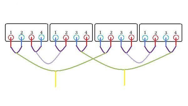
At one point I came up with this scheme specifically intended to minimize impedance but never tried it after discovering that the ' 2-3 section' mod was sufficient when combined with caps. I'd be very interested to see how you'd apply your 'd-cell' analogy to this one or even the 'e' scheme for that matter...
____ So then Bill, does that mean that you are actually being so kind as to offer to individually-test power-coil pairs that Bruce has rewound with whatever wire-gauge he chooses, BEFORE ever committing them to the assembly of the finalized stator-project ?
Not a problem.
-
DewCatTea-Bob
- Posts: 2897
- Joined: Sun Nov 01, 2009 10:53 am
- Location: Near SE side of Lake Michigan
Alt.stator-project Related-stuff
[quote= wcorey ...
" ...As well as increasing available power output by working their magic on the impedance issue! "
____ Firstly, I doubt that any reader knows exactly-what you're referring-to by "the impedance issue ".
____ Batteries combined with the test-circuit actually do (relatively slightly) INCREASE power-output from the tested charging-system, as their stored-power feeds the test-load during the nulls between DC.power-pulses.
__ Capacitors work their magic by storing any amount of excess/leftover power that the load didn't consume during the times that the DC.pulses were feeding the load, and then feed that stored-power to the load during the times between power-pulses,, thus just merely SEEMINGLY increasing power-output !
In actuality, capacitors can't possibly INCREASE the power-output,, but rather simply store & redistribute it, (IF there was any excess power leftover to be saved).
" During the earlier testing, the peak output often occurred at a higher than desired impedance so we found ourselves dependent on partially parallel stator wiring schemes that would lower impedance. "
____ I'm sidestepping here just to help clarify whats-what on that...
__ When we tested a mocked-up load-system that happened to have a very-low resistance (due-to emulating a powerful headlight), the test-load could-not obtain the maximum-power which the alternator was actually capable of producing because the alt.winding's impedance was greater than the test-load's resistance,, so-thus the greater share of the produced-power was rather being wasted by the stator-winding itself (instead of being made available for the load).
So the stator had to have it's power-windings rearranged to a less-series & more-parallel arrangement, so-as to lower stator-impedance so that more of the produced-power could then be transferred-out to rather become consumed by the test-load. _ And by 'matching' the stator-impedance with the test-load's resistance, we then got much-closer to feeding the load with MOST-all of the available-power, (which would thus-then allow us to more fully realize exactly how powerful the test-stator actually was) !
" After adding caps to the test setups the problem was much reduced and higher impedance had less impact "
____ I'd have-to better brush-up on the exact circuit to be more sure of exactly what's-what with it,, but I'm thinking that a bit of a 'tank-circuit' between the cap & stator may've obscured test-reading/results and sort-of fooled you into suspecting that the stator's exact impedance-amount had become unimportant.
It's rather likely that the test-load was-not EXACTLY-matched to the stator-impedance, and therefore the cap could then store any excess-power and redeliver it, thus obscuring the actual test-results,, or somewhat likewise, the cap itself could possibly have become a significant part of the load and screw-with the test-results. - (Cap.size can possibly make relatively significant influences on circuits.)
" Using only two sections, it may not be necessary to put them in parallel though three is probably pushing it. "
____ If you do the-math, two pairs in series has 4-times as much resistance as two pairs in parallel !
__ (Those who've gone-with the rather popular/simple series-arrangement, need-not be too concerned though, with their modification-choice,, so long as their load-system is kept on the low-demand side of power-consumption.)
" Not sure how much the thinner wire will effect this though. "
____ Since thinner-wire will increase resistance (of a power-coil pair),, a series-arrangement of a couple section/pairs would-not be much-good for anything (other than perhaps a 24v.system).
So a parallel-arrangement is mandatory for the project-stator (in-order to keep stator-resistance from getting too-high) !
__ We unfortunately need to use the thinner-wire however, so that MORE wire-length can then get fitted into the stator's restricted volume-space.
" I'd be very interested to see how you'd apply your 'd-cell' analogy to this one "
____ I'd be glad to do-so, if I could know that I understand it correctly.
" or even the 'e' scheme for that matter... "
____ The equivalent in AA-cells has already been posted. _ I've now posted another-version of it, here-below.
__ Please let me know if you don't agree that it correctly-represents the equivalent of the 'E-scheme' for you.
" Not a problem. "
____ Hear that Bruce ?
So I suggest that you get started at your earliest opportunity, to take some #24-gauge wire (give or take one gauge-size), and do a practice winding-job on the pair of bobbins which you already have and send your resulted power-coil pair to Bill for some testing.
Hopeful-Cheers,
-Bob
You do not have the required permissions to view the files attached to this post.
PLEASE NOTE... If this-post is not-yet signed-off with '-Bob', then I'm still in the process of completing it,, and if not also included with 'DCT' near bottom as well, then I may edit this post's wording at a later time. - Dct.Bob
Return to “Ducati Singles Main Discussions (& How to Join)”
Who is online
Users browsing this forum: Duccout and 43 guests