just because the component has two wires coming from it doesn't mean it's an SCR. I have seen some odd ball components and the Italians are responsible for a few. it could be that one of the wires is connected to the case and a redundant scheme is in play for the ground connection. it could also be that the case connection is insulated from the circuit and the two wires are simply the diode connection. This is why I like to have a schematic when I am discussing a circuuit. Bob do you have the schematic for this RR? And even if it is an SCR, then sourcing an appropriate component is not a big problem. once you figure out what is needed, I'd expect that they could be sourced for $10 or less, maybe much less. It might be an SCR, but John has referenced an article where the RR was rebuilt using a diode. So I thought a diode was probably what was in there. I can't see the actual connections of the two terminals as they enter the can of the components in question. I know I have seen a schematic that seems very similar to this RR used for an early 750 twin that did have SCR's as the rectifying components. that is an advance on the earlier designs, as the rectifier is allowed to be turned off when not needed and as such, power is not wasted when not needed and alternator and associated components get a gentler duty cycle.
Johns tests would not indicate an SCR, as an SCR must have forward bias and a positive on the gate to conduct. An SCR that you do the "flip flop" test as Bob describes it, would read open both ways if no positive were placed on the gate.
Mike
battery problems
Moderator: ajleone
-
DewCatTea-Bob
- Posts: 2897
- Joined: Sun Nov 01, 2009 10:53 am
- Location: Near SE side of Lake Michigan
Replacement Semiconductor Type
By: john jupiter...
" How and what would i need to buy to pull this off? "
____ The cheapest way-to-go would be to buy a Full-Wave bridge-rectifier, rated at least 10-amps & 100PIV. _ There's already been much covered about this subject at this w.site... So try our-own search-box for "Bridge-block" or "rect.block", and see if you don't find all you could want to learn about such.
" What should i be refering to "it" as if its more than a mere diode?? "
____ An 'SCR' type semiconductor. _ I'd guess any unit you might find that's the same physical size would fill-the-bill well enough.
____ Considering what Mike has now brought-up, it's still questionable as to WHICH of your two SCRs is the actual bad one. _ Do you gather what I'm meaning to get at ?
Hopeful-Cheers,
-Bob
PLEASE NOTE... If this-post is not-yet signed-off with '-Bob', then I'm still in the process of completing it,, and if not also included with 'DCT' near bottom as well, then I may edit this post's wording at a later time. - Dct.Bob
-
DewCatTea-Bob
- Posts: 2897
- Joined: Sun Nov 01, 2009 10:53 am
- Location: Near SE side of Lake Michigan
One Defective SCR
By: MotoMike...
" just because the component has two wires coming from it doesn't mean it's an SCR. "
____ Of course not, but in this case the component-casing is obviously grounded and certainly those yellow-wires & brown-wires are not randomly colored, and anyone paying attention to the past few posts ought realize what those colors must have passing through them.
Besides, how could mere power-diodes only, be controlled to do any kind of high-power charging-regulation ?
" Bob do you have the schematic for this RR? "
____ No, never have,, and the exact components within the internal block have been left a mystery to me.
" And even if it is an SCR, then sourcing an appropriate component is not a big problem. "
____ Never meant to indicate that such SCRs became obsolete out of production, only that the specific model-number of those units employed by Ducati, have no-doubt been replaced with updated-versions (probably many times) since the 70s.
" It might be an SCR, but John has referenced an article where the RR was rebuilt using a diode. "
____ Yes but certainly you ought realize that THAT was concerning the older narrow-case components.
" I know I have seen a schematic that seems very similar to this RR used for an early 750 twin that did have SCR's as the rectifying components. "
____ Probably so, as they were the same R/R.unit except for being 12-volt versions.
" as the rectifier is allowed to be turned off when not needed "
____ Probably part of the reason why jj hasn't noticed his headlight get any brighter when revving-up, as his battery was then fully charged, thus turning-off the rectifier/SCRs. _ (Whereas before, his light stayed un-brightened because his battery was too weak to then turn-on the SCRs.)
So it's possibly so that the R/R.unit only provides charging-output when the state of the battery's voltage-level is between 4v & (about)- 6.4v.
" Johns tests would not indicate an SCR, as an SCR must have forward bias and a positive on the gate to conduct. "
____ Right. _ (Have you not been reading all the previous related posts ?) _ That's what's been indirectly referred to when I (& the manual) have been saying that the rectifier needs to be "turned-on" (by at least "4volts").
__ As I was getting-at near the end of my last post to jj, the particular SCR that seemed to be the one that's not giving a meter-reading, may possibly be the (good) one that needs to be turned-on (with a voltage that's not too-low or too-high).
" An SCR that you do the "flip flop" test as Bob describes it, would read open both ways if no positive were placed on the gate. "
____ Right, (as generally conveyed a few posts back), and that's why I had asked jj to elaborate about the particular reading which his needle-pointer type meter had given, (yet had somewhat left us in the dark about).
Dukaddy-DUKEs,
-Bob
PLEASE NOTE... If this-post is not-yet signed-off with '-Bob', then I'm still in the process of completing it,, and if not also included with 'DCT' near bottom as well, then I may edit this post's wording at a later time. - Dct.Bob
-
MotoMike
- Posts: 487
- Joined: Wed Aug 04, 2010 3:40 am
Re: battery problems
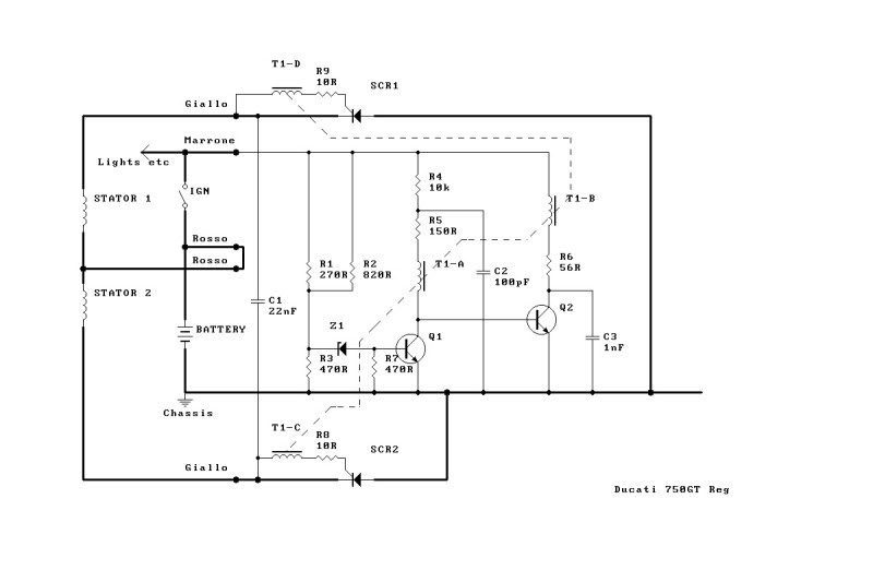
I've posted the schematic for the 750 in question. Bob do you think that is it?
No a power diode can't regulate by itself, but when you are dealing with a circuit that contains a mystery circuit or circuits inside a black box, the regulation could be taking place in there.
No a power diode can't regulate by itself, but when you are dealing with a circuit that contains a mystery circuit or circuits inside a black box, the regulation could be taking place in there.
Last edited by MotoMike on Thu Sep 15, 2011 3:38 pm, edited 1 time in total.
-
DewCatTea-Bob
- Posts: 2897
- Joined: Sun Nov 01, 2009 10:53 am
- Location: Near SE side of Lake Michigan
WideCase-type Rectifier/Regulator Internal Circuit-scheme
" Bob do you think that is it? "
____ Except for that which makes it 12v (instead of 6v), I would assume so,, but except for the pair of power-SCRs, I've never been able to have seen any of the internal-components (as everything's depicted to the right-side of 'C1', [all of which comprises the w-c R/R.unit] ).
__ I will colorize the diagram, especially if you care to provide any insight as to how that internal-circuit performs it's function.
But if that's done to a very fine degree, then it ought deserve it's own-thread !
Fun-Cheers,
-Bob
PLEASE NOTE... If this-post is not-yet signed-off with '-Bob', then I'm still in the process of completing it,, and if not also included with 'DCT' near bottom as well, then I may edit this post's wording at a later time. - Dct.Bob
-
john jupiter
- Posts: 160
- Joined: Wed Apr 06, 2011 1:00 pm
- Location: USA
Re: battery problems
Interesting stuff MM and DCTBob.. Although probably most of it is not fully understood by me, a guy who has never seen a circuit before..
So just to see if i am sort of on the right path..
Since i was never able to get a reading out of "scr diode" number two, but was able to get an acceptable reading out of diode number one..
Is it definite that one of the scr diodes is faulty or might it be possible that scr diode2 will get turned on during a ride when the battery is no longer fully charged?
Or is the fact that when i disconnect the negative ground from the battery and the engine immediatly stalls when in theory they scr diode should be turned on to keep it running indicate the scr diode2 in not able to be tunred on and is indeed fauty?
Might my problem have been the headlight all along and possible that without the 75watt light over taxing the charging system that without it, my system will go back into balance?
If there are any other angles or pics needed just let me know. Thanks guys!
JJ
1970 450 Jupiter
-
DewCatTea-Bob
- Posts: 2897
- Joined: Sun Nov 01, 2009 10:53 am
- Location: Near SE side of Lake Michigan
The Actual Problem is ?
" Since i was never able to get a reading out of "scr diode" number two, but what able to get an acceptable reading out of diode number one..
Is it definite that one of the scr diodes is faulty or might it be possible that scr diode2 will get turned on during a ride when the battery is no longer fully charged? "
____ I haven't bothered to test a w-c R/R.unit since the '80s, but I'm sure that both SCRs should measure-out the same.
To actually test them, (now that you have your unit removed from everything), the f/f ohm-test ought to be done with the unit left dead, and then again with about 5-volts fed to the brown-terminal. _ And hopefully while using a meter that gets to the point !
__ However after looking-over the schematic that Mike has posted, it may be that an ohm-meter -(alone) test will not be sufficient, and perhaps a center-tapped transformer (in place of the alt.) could be useful to fully check-out the charging-circuit's functionality.
(But for getting back on the road asap, just get yourself a handy bridge-block, from a RadioShack.)
" Might my problem have been the headlight all along and possible that without the 75watt light over taxing the charging system
, my system will go back into balance? "
____ The thought that your high-power light has led to the peculiar test-outcome of your R/R.unit, is as plausible any, I suppose. _ And replacing that light with a lower-power bulb will certainly help, but, until you can get a f/f ohm-test that leaves us more SURE of your R/R-unit's actual state, it currently seems that you have one bad SCR, (and thus your R/R.unit ought to be replaced with something).
Hopeful-Cheers,
-Bob
PLEASE NOTE... If this-post is not-yet signed-off with '-Bob', then I'm still in the process of completing it,, and if not also included with 'DCT' near bottom as well, then I may edit this post's wording at a later time. - Dct.Bob
-
john jupiter
- Posts: 160
- Joined: Wed Apr 06, 2011 1:00 pm
- Location: USA
Re: battery problems
Found a full wave rectifier at radio shack: http://www.radioshack.com/product/index ... Id=2062584
25a 50piv. It has 4 terminals on the top, 2 of them are labled ac, Does this replace only one of the scr diodes and the rest of the internald left inplace? Or do i need two of them and gut all the internals on my box?
25a 50piv. It has 4 terminals on the top, 2 of them are labled ac, Does this replace only one of the scr diodes and the rest of the internald left inplace? Or do i need two of them and gut all the internals on my box?
1970 450 Jupiter
-
DewCatTea-Bob
- Posts: 2897
- Joined: Sun Nov 01, 2009 10:53 am
- Location: Near SE side of Lake Michigan
Cheap FW.rect-block Use
" Found a full wave rectifier at radio shack:
25a 50piv. It has 4 terminals on the top, 2 of them are labled ac, "
____ And the odd-corner signifies the positive-output.
" Does this replace only one of the scr diodes and the rest of the internald left inplace? "
____ One of those have 4 diodes inside and can-not replace a SCR.
There are many options for you with such, but I was thinking you could just temporarily use one of those r.blocks until you fix your stock R/R.unit.
These r.blocks can be bolted to the frame in place of the stock R/R.unit, then the pair of yellow alt.wire-leads can be connected directly to the two AC-input terminals on the r.block, along-with it's neg.terminal connected to ground.
This will not provide any means of charging-system regulation but, for systems that are fairly-well balanced and employ a large enough battery, charging-regulation is then not really needed.
So in this case, (with both yellow AC.outputs left connected at all times), the lights should then be turned-on whenever running at over 4000-RPM for periods longer than about an hour, as doing so will then prevent the battery from getting overheated. _ (And by turning the lights on & off, the rider can manage system-voltage much the same as a regulator-circuit, [if need be].)
This very simple charging-setup will keep the available alt.power at maximum at all times and it will also be somewhat stronger than the stock-system ever manages to get, so at top-RPM there's a chance that the stock lighting-load could experience a filament burn-out if the battery is already fully charged (and thus not acting much as a load itself). _ But with stronger lighting than stock, the system-voltage will more likely be kept-down from being able to blow any lights, (as the system would be better balanced at higher-revs then).
__ For more permanent use of such a rectifier, the system can be kept balanced even better by not leaving the secondary yellow alt.wire-lead constantly connected (to one of the r.block's AC-inputs). _ Instead it's connection can go through an On/Off-switch, thus then allowing the rider still more control of the charging-system's effect on system voltage, by being able to cut alt.output-power when the lights are not turned-on, (for one [main]- example).
(More details on this to come, if interested.)
" Or do i need two of them and gut all the internals on my box? "
____ Well, yes, IF you wish to give-up on fixing the box's stock internals, yet wish to keep it LOOKING functionally-stock externally, and also, wish to increase your charging-system's power-output,, you could then fit-within, a couple (smaller-sized) FW.bridge-rectifiers, (also available at R.S.). _ However you're then looking at more work.
____ Sorry for not answering your questions more directly but, you should now gather that such r.blocks were never intended to be used as you seemed to have thought we might.
__ This could continue-on a number of different ways from this point, so I'll now wait for you to let us know which of the directions interest you enough for further info/guidance on them.
Fun-Cheers,
-Bob
PLEASE NOTE... If this-post is not-yet signed-off with '-Bob', then I'm still in the process of completing it,, and if not also included with 'DCT' near bottom as well, then I may edit this post's wording at a later time. - Dct.Bob
-
MotoMike
- Posts: 487
- Joined: Wed Aug 04, 2010 3:40 am
Re: battery problems
Bob
wanted to make sure the circuit was the right one before I studied it. . Of course the question comes as to the function of the common core inductors. they did not show the phasing dots, so some speculation as to what they are doing might be in order as one way they would impede current flow and one way aid. My initial impression is that they are being used to induce gate pulses to the scr's.
a simple scr tester can be made by connecting the positive of a 9 volt battery in series to a resister and then to the anode of the scr. connect the negative of the battery to the cathode of the scr and measure across the SCR with a volt meter. should be near applied voltage. with the meter still connected touch and then remove a jumper from the anode to the gate. voltage across the scr should drop to .7 or so and stay there. I'd try to keep the current as low as possible. If memory serves scr's can have holding currents from 1 to 50ma, so you'd need a total circuit resistance of about 180 ohms so a 150 or 160 ohm resistor should get you in the ball park. You'd need a .5 watt resistor in the described case to keep the resistor from burning up. even if it passes this test, it is not conclusive as the charging system bangs the scr pretty hard.
as for testing an scr with an ohm meter, I think the only connection that should give a high/low to the flip flop test is the cathode to gate connection as I think they are composed of one pn junction. the other tests, anode to cathode and anode to gate should read high/high. with that in mind, I don't know just what the high low reading on one side and open on the other that john got is telling us. when testing the scr, we need to make sure we have eliminated parallel paths for current. I'd probably unsolder the wires connected to the scr's at the easiest to get to connection and do the tests with them still held captive in the case.
Return to “Ducati Singles Main Discussions (& How to Join)”
Who is online
Users browsing this forum: No registered users and 40 guests