By: ecurbruce...
" Awesome! work, I'm excited(again). "
____ It shouldn't be TOO exciting for YOU Bruce ! _ As YOUR intended load-system will be closer to the 1-ohm outcome.
At this point, it seems you might hope to 'break-even' near 3500-RPM with a parallel-version (of the latest/straight-series arrangement).
Hopeful-Cheers,
-Bob
n-c alternator modifications: discussion and testing
Moderator: ajleone
-
DewCatTea-Bob
- Posts: 2897
- Joined: Sun Nov 01, 2009 10:53 am
- Location: Near SE side of Lake Michigan
Bill's New & Improved Test-results !
PLEASE NOTE... If this-post is not-yet signed-off with '-Bob', then I'm still in the process of completing it,, and if not also included with 'DCT' near bottom as well, then I may edit this post's wording at a later time. - Dct.Bob
-
ecurbruce
- Posts: 317
- Joined: Fri Apr 01, 2011 12:43 am
- Location: Hurricane mills TN
Re: 6volt or 12 volt?
Bob says:
____ It shouldn't be TOO exciting for YOU Bruce ! _ As YOUR intended load-system will be closer to the 1-ohm outcome.
At this point, it seems you might hope to 'break-even' near 3500-RPM with a parallel-version (of the latest/straight-series arrangement).
Bill has done quite a bit of work,for all of us, at times has been quite frustrating, at others I'm sure quite rewarding. As frustrating as I know it can be to come upon stumbling blocks and down turns, when one finally gets a breakthrough, and can proceed with (whatever they are doing) it can be quite exciting!!!!!!
Trust me, I AM painfully aware of the load demands that my system will require.
Having said that, yes, I am ready to see the parallel version, Bob, if everyone else is fully satisfied with the progress so far. I'd like to see a schematic (or drawing ) of the next proposed.
Bruce.
-
DewCatTea-Bob
- Posts: 2897
- Joined: Sun Nov 01, 2009 10:53 am
- Location: Near SE side of Lake Michigan
Preparing for Parallel-type Testing
" As frustrating as I know it can be to come upon stumbling blocks and down turns, when one finally gets a breakthrough, and can proceed with (whatever they are doing) it can be quite exciting!!!!!! "
____ Oh, I can understand that,, just thought you meant you were once again excited for having renewed hope for your own high load project.
" I AM painfully aware of the load demands that my system will require. "
____ No need to be "painfully" aware anymore, as plenty of power now seems to be within grasp.
" yes, I am ready to see the parallel version,
I'd like to see a schematic (or drawing ) of the next proposed. "
____ I think the next step (in a normal sequence-order), would be to simply test only one-half of the stator-winding, alone. _ Unfortunately, since the physical-layout won't allow for a simple tap into the MID-point, 'electrically', (so as to simply effectively test just one half of the complete stator-winding, as it's all currently wired-up), without undoing Bill's current solder-work,, it is therefore more logical (in manor of convenience) to test merely one-third of the current six coil-spool set-up, (which would be same as one-half of the stock four coil-spool setup).
The reason for testing only 1/3rd -(just 1-large & 1-small spool-pair worth of the entire stator-winding) at this time, is because THAT can be done with the individual coil-windings left soldered as is. _ (Whereas in order to test exactly one-half of the current entire alt.winding, most all of the present connections between the 12 individual coil-windings would then have to be redone.)
Then after that, test another 1/3rd (all-alone also),, so as to be sure that the stator-winding has been equally divided.
Then we could next calculate what the results ought to be with the two (1/3rds) connected in parallel fashion,, and then actually try testing such an arrangement.
__ After that, a best reconfiguration for a parallel arrangement of all 6 coil-spools to be tested, can be done.
____ Bill had mentioned a thoughtful desire to do the same type of testing on the four coil-spool setup as well, anyhow.
__ Anyone, please let me know if I haven't made it clear as to what's next to be done and why.
Onward-Cheers,
-Bob
PLEASE NOTE... If this-post is not-yet signed-off with '-Bob', then I'm still in the process of completing it,, and if not also included with 'DCT' near bottom as well, then I may edit this post's wording at a later time. - Dct.Bob
-
ecurbruce
- Posts: 317
- Joined: Fri Apr 01, 2011 12:43 am
- Location: Hurricane mills TN
Re: 6volt or 12 volt?
Bob,
New drawing... can you use this to configure new circuit?
New drawing... can you use this to configure new circuit?
You do not have the required permissions to view the files attached to this post.
-
DewCatTea-Bob
- Posts: 2897
- Joined: Sun Nov 01, 2009 10:53 am
- Location: Near SE side of Lake Michigan
Re: 6volt or 12 volt?
" New drawing... can you use this to configure new circuit? "
____WOW ! - That sure puts the one I was working-on to shame !
Yes, sure can ! _ I'll use yours to start showing what should be done next, (in most convenient order for Bill).
__ Hopefully Bill can also use your (details galore!)- drawing to show the present connections he's made to get his most-recent test-results.
____ I've added a modified-version of Bruce's detailed drawing of the alt.stator's 6-spool arrangement.
Without seeing a completed-version showing exactly how Bill already actually has the 12 coil-windings connected-up, there's a 50/50-chance that I have the indicated connections reversed (from how Bill has them). _ But in either case, the concept is displayed as to what section of the stator-winding is to be tested. ...
Connecting the test-circuit to just the 4 individual coil-windings (of a single pair of spools), at points '1' & '7',, will allow testing of just a 1/3rd-section of the "grand" straight-series stator-winding.
__ We have to proceed this way because the spools are paired-together as 1-small/1-large main-spool pairing, (and 3-pairs can't be divided-up to exactly '50/50' !). _ (In order to get two EQUAL stator-windings, Bill would have to reconnect most all the individual coil-windings, so as to end-up with two equal & separate parallel stator-windings.)
So conveniently at this point, Bill will not have to make any new coil-winding connections, he will only have to change the connection-points where he takes his test-measurements from.
____ More about the modified-drawing...
It now more properly shows the original 4 coil-spools shown located below 9 to 3 o'clock.
Each of the 6 coil-spools is shown as actually a dual-spool with two individual coil-windings - (1-inner & 1-outer). _ And the 6 separate main-spools ought be thought of as paired-couples - (1-small & 1-large), thus there's 3 such paired-couples, (of which only the lowest two pairs are stock).
You do not have the required permissions to view the files attached to this post.
PLEASE NOTE... If this-post is not-yet signed-off with '-Bob', then I'm still in the process of completing it,, and if not also included with 'DCT' near bottom as well, then I may edit this post's wording at a later time. - Dct.Bob
-
wcorey
- Posts: 323
- Joined: Sun Jan 31, 2010 1:50 am
- Location: MA USA
Re: 6volt or 12 volt?
" Revised figure on 14 ohm, not sure what happened with the last one. "
____ I thought you had done each of the past reported ohm-value tests twice ?
Could it be possible that the stator was at a different temperature between then & your latest trial ?
I added on that (then) last 3 ohm resistor after I did the initial round, so everything but the 14 ohm was double tested. For some reason I get odd readings once in a while that I can't duplicate, for instance I swore in the night before quick-y test I got ~88w at 3 ohms. When I do a big series of tests, I set each up, spin up the motor and as soon as the readings are stable ( a few seconds) I snap a pic. Most of the time I don't even pay attention to what the actual readings are until I look at the pics afterward so if something is slightly amiss I don't catch it until after the fact.
download/file.php?id=604&mode=view
Nice drawing Bruce! With something like this a change can be described by just referencing this number goes to that number on this letter, without having to redo the drawing every time.
The problem I have with it is that for my purposes it doesn't translate well for me, to the actual physical layout I see when looking at the stator. With yours the consecutive wire numbers don't coincide with how they come out of the spools, I have to do an adapted version of it to get the visual I need to start rerouting wires. What works for me is what I've been talking about with the boxes with four wires in a row, just like looking at the bottom of a coil spool.
Another thing that would be helpful is if there was like a little radius at the end of each wire where it goes into the coil, giving some indication of winding direction.
This is how I make sense of it, breaking it down to it's most simple form, a basic block version of what I actually see. In this pic it's also the present grand series layout of the stator being tested, odd numbers are large coils, even are small. Blue and red represent outer and inner windings, don't know which is which. I didn't want to clutter it with more numbers but the connections can be referred to as 1 through 4 or a through d on each block, going clockwise. The transposed arrangement of #1 is not an error, that's the way it is...
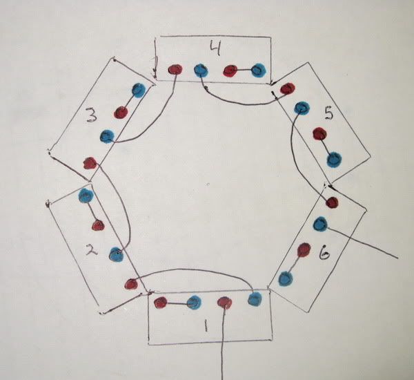
This is a blank so anyone can use it, either with a paint program or to print it and draw on it then rescan or snap a photo of it.

Bob, It's funny you want to split it into three groups of two, I was waiting to make sure no one wanted anything else from the present setup and was going to do just that but to try it on a three phase rec/reg. Would that be a waste of time?
Another thing I meant to ask some time ago when I was doing the dual rec full wave series/parallel setups. Could the outputs of the rec's be combined in parallel?
Bill
-
DewCatTea-Bob
- Posts: 2897
- Joined: Sun Nov 01, 2009 10:53 am
- Location: Near SE side of Lake Michigan
Next Stator-segment Test-scheme
____ Here's the next proposed segmented stator-winding test-scheme.
Actually, it's up to Bill as to the particular order of the next three batches of tests.
I understood that he wanted to do a test of just the original 4 coil-spools while still connected-up in the currently-present grand-like straight-series fashion. _ And that actually is a simple straight-forward test-arrangement to try-out, as he only has to make his test-connections to terminal-points '1' & '11', (so as to test just the 4 original coil-spools combined in 'series'). _ That will then test only two of the currently-present three pairs of coil-spools (without requiring any changing of the last-established stator-connections).
__ So while Bill's stator is connected-up just as it is, he can choose to test either the lower-right coil-spool pair, or the lower-left coil-spool pair, or, both together in combined-series,, in whatever order he sees fit.
We just wish to know what the original 4 -(two pairs/segments) of coil-spools will produce (with the straight-series type arrangement), and also what both of it's halves/segments will do independently. ...
That is to say in other words, of the 3-pairs/segments (of the 6-pole stator), we wish to know the power-output of just one segment/pair (of coil-spools), plus also that of the other segment/pair, (all of the original spools),, plus also, both segment/pairs together in series (just as they already are).
So that's three different tests... Tests with outcomes which may not be able to be calculated, because it's unknown what the segmented stator-windings' working-impedance will turn-out to be.
You do not have the required permissions to view the files attached to this post.
PLEASE NOTE... If this-post is not-yet signed-off with '-Bob', then I'm still in the process of completing it,, and if not also included with 'DCT' near bottom as well, then I may edit this post's wording at a later time. - Dct.Bob
-
DewCatTea-Bob
- Posts: 2897
- Joined: Sun Nov 01, 2009 10:53 am
- Location: Near SE side of Lake Michigan
Three Segmented Stator-windings Arranged in Prarallel
By: wcorey...
" It's funny you want to split it into three groups of two, "
____ Well it's not that I really WANT to, it's just that there's no way to divide-up the present single stator-winding exactly in half 'electrically' (due to the small & large pairings), until you can reconnect all the individual coil-windings so as to have two separate & equal stator-windings. _ But in the mean-time, you already have the stator connected-up as it needs to be in order to do the tests which I've proposed/covered in my last two previous postings.
" I was waiting to make sure no one wanted anything else from the present setup and was going to do just that "
____ There would've been no reason to wait Bill, as that "present setup" is already just as needed for either, so you could've proceeded, and it would still remain same if anyone did indeed want more testing of it as is.
" but to try it on a three phase rec/reg.
Would that be a waste of time? "
____ I was also wondering about that possibility but, don't know if your R/R-unit can handle the power when it's all 'in-phase'.
The resulting impedance of that alt.power-circuit ought be under 2-ohms, but it's hard to be sure of what the actual working-impedance will end-up being, before an actual test.
__ What you'd do is connect all three segment/pairs to a 'common-lead', and each of their opposite-polarity leads to the three respective inputs (intended for triple-phase) on your 3-phase R/R-unit,, and with those three plus the common-lead input-connections all made, you could then test the output from your R/R-unit.
But it would be preferred if you'd first get all the requested-tests completed before-hand.
" Another thing I meant to ask some time ago when I was doing the dual rec full wave series/parallel setups. Could the outputs of the rec's be combined in parallel? "
____ Yes of course, since you'd be expected to blend only the POSITIVE-outputs together, (while both negative-outputs would be grounded),, which is pretty-much the very same thing that your multi-input R/R-unit does, btw.
____ Concerning your drawing, it seems we're going to need Bruce to insert it's likeness into the very-center of his-own drawing, and then show how which of HIS numbered lead-ends correspond to which of YOUR physically-placed terminal-spots.
Fun-Cheers,
-Bob
PLEASE NOTE... If this-post is not-yet signed-off with '-Bob', then I'm still in the process of completing it,, and if not also included with 'DCT' near bottom as well, then I may edit this post's wording at a later time. - Dct.Bob
-
ecurbruce
- Posts: 317
- Joined: Fri Apr 01, 2011 12:43 am
- Location: Hurricane mills TN
Re: 6volt or 12 volt?
Bob says;"____ Concerning your drawing, it seems we're going to need Bruce to insert it's likeness into the very-center of his-own drawing, and then show how which of HIS numbered lead-ends correspond to which of YOUR physically-placed terminal-spots."
Yes, I can work on that tonight, thanks, that's just the kind of input that I need for the drawings. Does it work better drawn in a circle, or in a straight row? (or one of each)
Bruce.
Yes, I can work on that tonight, thanks, that's just the kind of input that I need for the drawings. Does it work better drawn in a circle, or in a straight row? (or one of each)
Bruce.
-
MotoMike
- Posts: 487
- Joined: Wed Aug 04, 2010 3:40 am
Re: 6volt or 12 volt?
man, you guys are doing the heavy lifting now. Good job. I wait with bated breath.
Return to “Ducati Singles Main Discussions (& How to Join)”
Who is online
Users browsing this forum: No registered users and 78 guests