Bill, those are some pretty impressive numbers with your regulator inserted.
I'm wondering what those numbers would look like at a slower speed, you don't have a speed controller to put on that electric motor do you? You could carry the speed down until you found the "break even" point on each setup!
Bruce.
n-c alternator modifications: discussion and testing
Moderator: ajleone
-
ecurbruce
- Posts: 317
- Joined: Fri Apr 01, 2011 12:43 am
- Location: Hurricane mills TN
-
wcorey
- Posts: 323
- Joined: Sun Jan 31, 2010 1:50 am
- Location: MA USA
Re: 6volt or 12 volt?
" Same as first test but with addition of 3ohm res and 5ohm coil
4310rpm---9.95a---11.96vdc---119w "
It would be of interest to do this test with the 3-ohm resistor replaced by your battery.
4310rpm---9.21a---13.43vdc---123.59w
____ The testing with the higher power indicates that the employed regulator is working well. _ However it would be good to test the regulator at max.RPM with NO connected load, so as to see that it can indeed handle it's job when not given any help by the loads. _ I'd say that any resulted voltage higher than 14.6v, is failing (especially when a battery is added to the circuit).
6k rpm, no load, 14.8vdc (typical of many of my reg's, I doubt they're all failing...)
I'm wondering what those numbers would look like at a slower speed, you don't have a speed controller to put on that electric motor do you? You could carry the speed down until you found the "break even" point on each setup!
The problem there is I'd have no way of knowing what rpm it's running at, while with the pulley system it's simple measurement/math.
Bill
-
DewCatTea-Bob
- Posts: 2897
- Joined: Sun Nov 01, 2009 10:53 am
- Location: Near SE side of Lake Michigan
Tested R.R-unit... "3 phase" or not ?
By: wcorey...
" It's a three phase reg, has three inputs like all the other three phase reg's I have,"
____ Right, I had figured that's the type of R.R-unit you had, and I'm glad you've confirmed that it's like most other 3-phase type units... All such units that I've ever known of, have 3 separate std.type inputs - 1 input for each of the three phased outputs (of the 3-phase alt), PLUS the 'common' input, for a total of 4 separate inputs -(input-terminals).
I now assume that what you must have actually meant, was just three separate 'pairs' of inputs,, which is a total of six wire-connections between the 3-phase alternator & the R.R-unit. _ But three of the six can be combined into just one connection, thus making the 4th wire a "master-type" 'common' wire (for 1, plus the other 3, for 4 total inputs).
Does this now clear-up our confusion on this issue ?
" never seen or heard of a 'master-type 'common' input' on one. Even single phase alt's have two output leads. What is the function/use of a 'master-type 'common' input'? "
____ It's function is to simply cut-down on excess wiring ! ...
It's understood that a 'single-phase' NEEDS one pair of connecting-leads (for it's single pair of outputs), but while a 3-phase would thus seem to require the use of three pairs, it actually only needs three single connections plus one 'common' -(master-type) connection-lead, (which must handle all the opposite polarities of each of the three separate/phased power-outputs), thus saving two lengths of wire-connections plus their related output and input terminals !
Do I need to draw-up a digram ?
__ I don't understand why this wasn't already clear to you... Does yours really have three full 'pairs' of inputs ?
____ That doesn't make sense to me ! _ I'm now thinking that perhaps your supposed '3-phase' type R.R-unit is possibly just a 2-phase unit. _ As a 2-phase R.R-unit would have 1 'common' input, plus 2 std.type inputs -(one for each phase).
So this could be the actual solution to our prior confusion-issue, (if your R.R-unit actually only has just three SINGLE inputs).
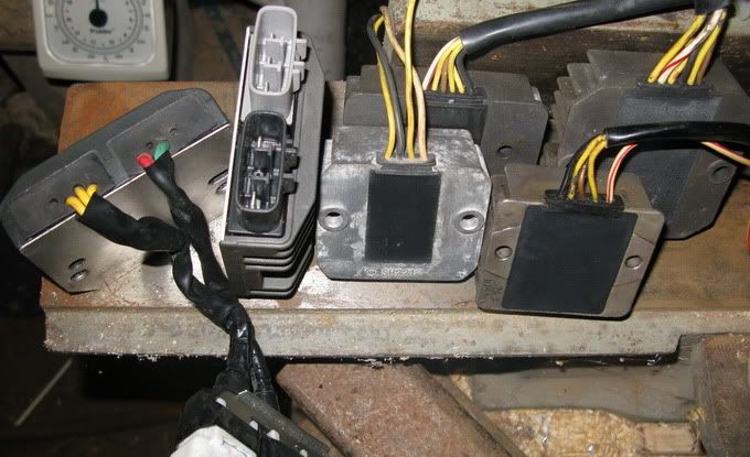
__ Do you have any pix of your chosen R.R-unit ?
" No, my bad for not being more clear. The 'first test' is with just the light. "
____ Got it... as I continued studying-through your posting, I then came to gather that as likely being the actual case.
____ Yes, that's no doubt somewhat true, (and even more-so if your chosen 25-ohm resistor is not a wire-wound type). ...
A 25-ohm resistor would draw about .5-amps (of straight-line DC), constantly,, whereas the ign.circuit would create a pulsating-DC through the coil type load, which would actually increase the 'impedance' of the circuit and thus be more restrictive to current-flow than just the (presumed measured) 5-ohms of 'resistance' (to straight-DC through the ign.coil).
So this means that perhaps a 30-ohm resistor would be even closer to ACTUAL working-reality.
But in any case, I had figured that the 25-ohms would be close enough since (in this case) it would be best to go with a current-draw that's on the HIGHer side of what might be actual.
(BTW, the "20%" which I had come-up with, was also rounded-upward towards the high-side.)
____ Seems the battery draws less juice than the resistor, yet it better maintains system-voltage (than with the capacitors alone).
____ When I used the word "failing", I didn't mean to imply the word as if to say that a regulator is beginning to go-bad,, rather, I merely meant that it's my opinion that a 12v.regulator is failing to do it's intended job well enough, whenever system-voltage exceeds 10% greater than a fully-charged (13.2-volt) battery.
Since that regulator had allowed such a high voltage (as 14.8v), I'd say that it's meant to depend on a std.battery for help (with holding-down the voltage-level).
" It's a three phase reg, has three inputs like all the other three phase reg's I have,"
____ Right, I had figured that's the type of R.R-unit you had, and I'm glad you've confirmed that it's like most other 3-phase type units... All such units that I've ever known of, have 3 separate std.type inputs - 1 input for each of the three phased outputs (of the 3-phase alt), PLUS the 'common' input, for a total of 4 separate inputs -(input-terminals).
I now assume that what you must have actually meant, was just three separate 'pairs' of inputs,, which is a total of six wire-connections between the 3-phase alternator & the R.R-unit. _ But three of the six can be combined into just one connection, thus making the 4th wire a "master-type" 'common' wire (for 1, plus the other 3, for 4 total inputs).
Does this now clear-up our confusion on this issue ?
" never seen or heard of a 'master-type 'common' input' on one. Even single phase alt's have two output leads. What is the function/use of a 'master-type 'common' input'? "
____ It's function is to simply cut-down on excess wiring ! ...
It's understood that a 'single-phase' NEEDS one pair of connecting-leads (for it's single pair of outputs), but while a 3-phase would thus seem to require the use of three pairs, it actually only needs three single connections plus one 'common' -(master-type) connection-lead, (which must handle all the opposite polarities of each of the three separate/phased power-outputs), thus saving two lengths of wire-connections plus their related output and input terminals !
Do I need to draw-up a digram ?
__ I don't understand why this wasn't already clear to you... Does yours really have three full 'pairs' of inputs ?
" Tried it already but got very low output, like a couple volts. "DCT-Bob wrote:...you ought to connect each of the three sections to a dedicated input on the R.R-unit, (as expected for a 3-phase type unit, [even though being fed a single phase]).
____ That doesn't make sense to me ! _ I'm now thinking that perhaps your supposed '3-phase' type R.R-unit is possibly just a 2-phase unit. _ As a 2-phase R.R-unit would have 1 'common' input, plus 2 std.type inputs -(one for each phase).
So this could be the actual solution to our prior confusion-issue, (if your R.R-unit actually only has just three SINGLE inputs).
__ Do you have any pix of your chosen R.R-unit ?
" No, my bad for not being more clear. The 'first test' is with just the light. "
____ Got it... as I continued studying-through your posting, I then came to gather that as likely being the actual case.
" Wouldn't that result in a different working impedance than the coil? "DCT-Bob wrote:But (in working reality), the ign.coil will only be drawing about 1/5th as much current, (so to represent that, a 25-ohm resister ought to be substituted in it's place).
____ Yes, that's no doubt somewhat true, (and even more-so if your chosen 25-ohm resistor is not a wire-wound type). ...
A 25-ohm resistor would draw about .5-amps (of straight-line DC), constantly,, whereas the ign.circuit would create a pulsating-DC through the coil type load, which would actually increase the 'impedance' of the circuit and thus be more restrictive to current-flow than just the (presumed measured) 5-ohms of 'resistance' (to straight-DC through the ign.coil).
So this means that perhaps a 30-ohm resistor would be even closer to ACTUAL working-reality.
But in any case, I had figured that the 25-ohms would be close enough since (in this case) it would be best to go with a current-draw that's on the HIGHer side of what might be actual.
(BTW, the "20%" which I had come-up with, was also rounded-upward towards the high-side.)
" 4310rpm---9.21a---13.43vdc---123.59w "wcorey wrote: with addition of 3ohm res and 5ohm coil
4310rpm---9.95a---11.96vdc---119w "DCT-Bob wrote:It would be of interest to do this test with the 3-ohm resistor replaced by your battery.
____ Seems the battery draws less juice than the resistor, yet it better maintains system-voltage (than with the capacitors alone).
" 6k rpm, no load, 14.8vdc (typical of many of my reg's, I doubt they're all failing.. "DCT-Bob wrote: it would be good to test the regulator at max.RPM with NO connected load, so as to see that it can indeed handle it's job when not given any help by the loads. _ I'd say that any resulted voltage higher than 14.6v, is failing (especially when a battery is added to the circuit).
____ When I used the word "failing", I didn't mean to imply the word as if to say that a regulator is beginning to go-bad,, rather, I merely meant that it's my opinion that a 12v.regulator is failing to do it's intended job well enough, whenever system-voltage exceeds 10% greater than a fully-charged (13.2-volt) battery.
Since that regulator had allowed such a high voltage (as 14.8v), I'd say that it's meant to depend on a std.battery for help (with holding-down the voltage-level).
PLEASE NOTE... If this-post is not-yet signed-off with '-Bob', then I'm still in the process of completing it,, and if not also included with 'DCT' near bottom as well, then I may edit this post's wording at a later time. - Dct.Bob
-
wcorey
- Posts: 323
- Joined: Sun Jan 31, 2010 1:50 am
- Location: MA USA
Re: 6volt or 12 volt?
Does this now clear-up our confusion on this issue ?
No, I guess I'm still missing the point somewhere somehow.
The typical reg/rec that I have has either 2 or 3 yellow input wires (depending on whether single or 3 phase), and two output wires (pos/neg), a red or red/white and a black or green. Some have an additional brown wire that goes to the ignition switch and I believe 'shuts off' the reg when not in use so the battery can't drain back through it, eliminating the need for a heavier cutout switch that would otherwise be required to handle the full current load of the battery.
The typical stator I have has either 2 or 3 output yellow wires (depending on whether single or 3 phase) that connect to the reg/rec. The red/pos goes to the bat and the black/neg is ground.
The Shindengen 3ph mosfet units have five connections, three inputs and two outputs, the FH008's have a pigtail to the connectors and the FH010/11/12's have the connectors on the unit directly. When used as single phase, the two (yellow) stator wires go to any two of the (yellow) reg/rec inputs and the pos/neg go to the load (bat/cap/light/whatever).
Since that regulator had allowed such a high voltage (as 14.8v), I'd say that it's meant to depend on a std.battery for help (with holding-down the voltage-level).
I'd assume that the vast majority of reg's that come on modern stock street bikes are designed the be used with a battery.
Bill
Last edited by wcorey on Sun Jul 10, 2011 1:01 am, edited 1 time in total.
-
DewCatTea-Bob
- Posts: 2897
- Joined: Sun Nov 01, 2009 10:53 am
- Location: Near SE side of Lake Michigan
Types of 3-phase Alternator Internal-connection Methods
" No, I guess I'm still missing the point somewhere somehow. "DCT-Bob wrote:Does this now clear-up our confusion on this issue ?
____ Yeah, I guess I now understand why...
I was considering drawing-up the circuit myself, to post-up but, instead found a ready-made one which not only shows the two types I was fully aware of, but also a Delta-type version (of a 3-phase alt, which I had failed to have considered as being the type which your 3-input R.R-unit is probably intended for) !
NOW I'm thinking that if you're sure that your R.R-unit is indeed meant for a THREE-phase alt, then it's most likely got to be meant for a delta-type internal-connection alt.arrangement.
__ As can be seen in the posted-pic, not only depicted are the two types of arrangements which I had already touched-upon -(types "A" & "B"), but also the (previously overlooked) "DELTA" version -(type "C") is shown as well.
Type-A would have the full three pairs of outputs, while type-B makes use of a 'common' lead -(which within the depiction is indicated as "NEUTRAL"), and so thus has it's three std.type outputs, plus a single master-type main-output (for only four, in total). _ (The reason I had not used the term 'neutral' for the main/common-output, is simply because it wasn't descriptive-wording.)
Type-C is a (somewhat odd but simplistic and fairly named) delta-version,
and may very well be the type that your R.R-unit is particularly intended for,
and this type requires only six diodes (for complete full-wave rectification).
__ NOW, (with this picture-assisted posting), I expect that what I've been trying to convey before, finally all makes perfect sense to you,, does it not ?
And so now you should ought to understand how I had expected that a 3-phase R.R-unit (meant for either type-A or type-B), should work fine with the three-sectioned modded Ducati alt.stator.
Considering that you stated all your R.R-units have the same number of inputs, I'm now concerned that it may be difficult to obtain one with the std.3 + 1-main/neutral input-arrangement, (as expected for type-B).
Hopeful-Cheers,
-Bob
You do not have the required permissions to view the files attached to this post.
PLEASE NOTE... If this-post is not-yet signed-off with '-Bob', then I'm still in the process of completing it,, and if not also included with 'DCT' near bottom as well, then I may edit this post's wording at a later time. - Dct.Bob
-
DewCatTea-Bob
- Posts: 2897
- Joined: Sun Nov 01, 2009 10:53 am
- Location: Near SE side of Lake Michigan
Three-phase Rectifier-connections
____ I'm now including a scheme-drawing of the rectifier setup that's likely within Bill's R.R-unit (that's intended for a 3-phase alternator).wcorey wrote:Tried it already but got very low output, like a couple volts.DCT-Bob wrote:you ought to connect each of the three sections to a dedicated input on the R.R-unit, (as expected for a 3-phase type unit, [even though being fed a single phase]).
I'm not previously familiar with the Delta-type 3-phase alternators & R.R-units but they seem pretty simple, as can be noted in the drawing.
I still think that the three-sectioned extra-modded 6-pole alt.stator could be connected-up to Bill's 3-phase type R.R-unit...
I suspect that the reason the power-output was so low when he tested the combined setup, is cuz without an input (on his particular/chosen R.R-unit) to connect a 'common' / "neutral" lead (from the three stator-sections) to,, the only output available then, would be any DIFFERENCEs (in output) between the three stator-sections -(I, II, & III), (as it has been previously noted that 'se.II' is slightly weaker than se.I & se.III).
__ I believe the correct solution to proper connection of the three-sectioned stator to Bill's 3-phase R.R-unit, is to consider each of the indicated green-lines as a PAIRed-up couple of wire-leads - (1 wire + 1 wire, both coming from each of the three connection-points between the ends of each of the three stator-loops, [if that helps make added sense of the intended notion] ).
___ So Bill, are you now interested in trying-out that 3-phase R.R-unit test again (with the three additional wire-leads properly paired & connected-up) ?
Hopeful-Cheers,
-Bob
You do not have the required permissions to view the files attached to this post.
PLEASE NOTE... If this-post is not-yet signed-off with '-Bob', then I'm still in the process of completing it,, and if not also included with 'DCT' near bottom as well, then I may edit this post's wording at a later time. - Dct.Bob
-
wcorey
- Posts: 323
- Joined: Sun Jan 31, 2010 1:50 am
- Location: MA USA
Re: 6volt or 12 volt?
__ I believe the correct solution to proper connection of the three-sectioned stator to Bill's R.R-unit, is to consider each of the indicated green-lines as a PAIRed-up couple of wire-leads - (1 wire + 1 wire, coming from each of the ends of each of the three sections, [if that helps to make sense of it] ).
I'm unclear on this, sounds like you want to short each section to itself then connect each shorted section to the reg/rec inputs? Otherwise how do six wires go to three inputs?
Seems like I'd need a reg made for a 'wye' configured alt to have a chance of it working.
An interesting thing about the 'wye' configuration is that it puts out higher voltage at lower rpm (and higher peak wattage output) than the 'delta' type but the delta has a lower working impedance.
___ So Bill, are you now interested in trying-out that 3-phase R.R-unit test again (with the three additional wire-leads properly paired & connected-up) ?
You should know by now I'll try almost anything once, lol... Thankfully with the alternator testing it's unlikely to blow something up assuming nothing stays running for very long.
Bill
-
DewCatTea-Bob
- Posts: 2897
- Joined: Sun Nov 01, 2009 10:53 am
- Location: Near SE side of Lake Michigan
Connections for 3-Phase
" I'm unclear on this, sounds like you want to short each section to itself then connect each shorted section to the reg/rec inputs? "wcorey wrote:__ I believe the correct solution to proper connection of the three-sectioned stator to Bill's R.R-unit, is to consider each of the indicated green-lines as a PAIRed-up couple of wire-leads - (1 wire + 1 wire, coming from each of the ends of each of the three sections, [if that helps to make sense of it] ).
____ Okay, this is one of those (fairly common) times when the chosen wording makes fair sense to the writer, but the reader sees that the wording can be taken quite differently (than was intended).
__ Anyhow Bill, did you not look-over my included drawing, as well ? _ Cuz I had expected that my posted-wording combined along-with the included wiring-scheme, to allow what I had meant to convey, to be properly deduced.
Perhaps you thought my (questionable)- wording was only meant to be in reference to just the three-sectioned Ducati-stator, (when actually, I was more-so meaning to be in regards to the depicted delta-arrangement).
Whatever,, I've now repaired that quoted-wording, to make less-mistakable sense.
" Otherwise how do six wires go to three inputs?
Seems like I'd need a reg made for a 'wye' configured alt to have a chance of it working. "
____ That's what I had thought too, but have been playing with the scheme in my head and now think it could still be done.
__ I've now made added detailing to the previous delta scheme-drawing which should better clear-up the confusion left by my previously chosen wording. _ So now instead of having to imagine the indicated green wire-leads as each being a 'pair' of wire-connections, ya can now SEE them as paired-up together, (one green & one yellow, x3), from the delta-stator all the way to the 3-phase type rectifier's indicated set of three input-terminals.
__ And also besides that, I've now included another drawing (within black-background), to correspondingly represent the three-sectioned Ducati-stator, as it ought to be ready wire-configured for connecting-up to your 3-phase R.R-unit. _ (The colors of green & yellow bear no significance and were just used only due to convenience-sake, although their relationship remains consistently correlated between the two drawings !)
" An interesting thing about the 'wye' configuration is that it puts out higher voltage at lower rpm (and higher peak wattage output) than the 'delta' type but the delta has a lower working impedance. "
____ Seems you've dug-up some related info,
however I'm somewhat doubtful of those stated differences.
Hopeful-Cheers,
-Bob
You do not have the required permissions to view the files attached to this post.
PLEASE NOTE... If this-post is not-yet signed-off with '-Bob', then I'm still in the process of completing it,, and if not also included with 'DCT' near bottom as well, then I may edit this post's wording at a later time. - Dct.Bob
-
wcorey
- Posts: 323
- Joined: Sun Jan 31, 2010 1:50 am
- Location: MA USA
Re: 6volt or 12 volt?
Perhaps you thought my (questionable)- wording was only meant to be in reference to just the three-sectioned Ducati-stator, (when actually, I was more-so meaning to be in regards to the depicted delta-arrangement).
If that had read; "... to the depicted delta-arrangement of the three sectioned alt.", it would have made all the difference (assuming that's what you meant).
When you state;
I still think that the three-sectioned extra-modded 6-pole alt.stator could be connected-up to Bill's 3-phase type R.R-unit...
And;
__ I believe the correct solution to proper connection of the three-sectioned stator to Bill's R.R-unit...
And;
___ So Bill, are you now interested in trying-out that 3-phase R.R-unit test again (with the three additional wire-leads properly paired & connected-up) ?
Considering I'm not testing an actual delta alt and even if I was they don't have or need 6 output wires, I don't see how all of the above can be taken any other way than that you're referring to the three section alt...
And if you are referring to the three section alt, then you mean to say that the new wiring scheme is supposed to emulate a delta alt on the three section setup? That would have been much easier to comprehend if you had used our standard drawing of it or at least stated that the drawing you used is meant to depict it. In your previous illustration of the A, B and C 3ph alt types, the 'A' is not one I'm familiar with but assumed is was some original older type or some such thing and not meant to depict our three section.(?)
Anyway, the newest arrangement (of the three-sectioned stator 'delta emulation' to the FH008 rec/reg as I think is depicted in bobs illustration) produced more or less the same failed result as the 'other' way, about 4vdc with the caps and no load, 156mv with a load.
" An interesting thing about the 'wye' configuration is that it puts out higher voltage at lower rpm (and higher peak wattage output) than the 'delta' type but the delta has a lower working impedance. "
____ Seems you've dug-up some related info,
however I'm somewhat doubtful of those stated differences.
Not that internet info is always reliable but I got that from multiple sources, the simplest most concise description is here: http://www.windstuffnow.com/main/3_phase_basics.htm and read:
"There are basically two ways to wire a 3 phase alternator, star ( or Wye) and Delta. With Delta you get lower voltage but more amps. In star you get higher voltage but less amps. You can calculate these by using the square root of 3 ( or 1.732 ). Each coil set is a "phase" of the alternator so when you measure voltage,ohms or current to test one phase of the alternator you would measure the "phase". Once you know what the output will be from one phase you can calculate the "line" output of either delta or star. The line voltage would be measured from any 2 of the 3 outputs. If one phase measured 22 volts in your test and 10 amps then the star configuration would produce 38 volts and 10 amps ( 22 x 1.732 ). The amps remain the same as the phase measurement because the star is basically series'd to another phase. In Delta you would get 22 volts at 17.32 amps (10 amps x 1.73 ). If you calculate this out 22 volts x 17.32 = 381 watts and 38 x 10 = 380 watts... so what is the advantage? Typically the resistance in Delta is 1/3 the resistance of star. If the resistance of star was 1.5 ohms we could calculate the output ( see formula section ). Lets assume the test was at 600 rpm, we achieved 38 volts in star ( about 16 rpm per volt ) so at 1000 rpm we would get 62.5 volts less battery voltage of 12.6 = 49.9 volts / 1.5 ohms = 33.26 amps * 12.6 = 419 watts... not to bad. Now in delta we had 22 volts at the same rpm ( about 27 rpm per volt ). So at the same 1000 rpm we get 37 volts - 12.6 battery = 24.4 volts / .5 ohms = 48.8 amps * 12.6 = 614 watts. Almost a 200 watt gain !!! The advantage of star is the higher voltage at lower rpm which means our unit would have to make 201 rpm to start charging at 12.6V where the Delta would require 340 rpm to start charging."
Bill
-
DewCatTea-Bob
- Posts: 2897
- Joined: Sun Nov 01, 2009 10:53 am
- Location: Near SE side of Lake Michigan
Misunderstanding Confusion
____ Well, this has evidently developed into a somewhat extra tangled-up mess of extended confusion ! _ (And it's really not worth trying to get all straightened-out really either.)
We've gone from a slight misunderstanding into a deeper & more complex mess of it. _ One which most people would avoid bothering to face up to and just choose to ignore.
But I'll give a go at trying to straighten it out a bit. _ Just hope my minor attempts help-out adequately enough. .....
(Guess I should've also completely capitalized "Perhaps" at the start.)
__ I hope this now clears-up the fact that I was indeed always meaning to be in reference to the three-sectioned project-stator, EXCEPT when having meant to refer to the delta-drawing itself. _ (I guess this kind of confusion is the price one pays for lazily making use of pre-existing drawings.)
" Considering I'm not testing an actual delta alt and even if I was they don't have or need 6 output wires, I don't see how all of the above can be taken any other way than that you're referring to the three section alt... "
____ Indeed Bill, (as again, I had only meant to make my minor-note concern ONLY that particular reference of mine to the delta-drawing). _ Thus of course I was otherwise always meaning to be in-reference to the project -(three-sectioned) alt.stator, with the only slight exception being just that one somewhat minor reference to the 'delta-diagram', (which you had found to be unclear).
__ Besides convenience-sake, I used that delta-diagram because, not only did I think it depicted the rectifier (which I thought you had), but also because that depicted representation of the delta-stator could just as well represent the three-sectioned project-stator (providing that the viewer could 'imagine' it's three green-leads as being three combined-pairs of wire-leads).
Indeed I had assumed that the viewers could 'see' that that supposed delta-stator depiction could also fairly-well represent the three-sectioned project-stator, (as expected !).
" And if you are referring to the three section alt, then you mean to say that the new wiring scheme is supposed to emulate a delta alt on the three section setup? "
____ Yes, providing that delta-depiction accurately electrically-represents a delta-type alt.stator configuration, (which I'm now guessing it might not actually do).
According to the connection-scheme (somewhat questionably) depicted for the delta-type alt.stator, it simply (cheaply!) allows one wire-lead to take the place of two, by INTERNALLY connecting the three separate stator-windings at their ends (delta-style), so they can thus have their winding-ends share just the one wire-lead, (x3, for those three internal-connections).
So yes, my suggested wiring-connection scheme should obviously allow the three-sectioned project-stator's three pairs of output-wires to be condensed-down to just three single connections (to such a 6-diode type rectifier), thus indeed "emulate" that of the delta-type setup.
As it obviously doesn't matter electrically, whether the (condensing like)- connections are made/done internally, or completed otherwise.
" then you mean to say that the new wiring scheme is supposed to emulate a delta alt on the three section setup? "
____ Yes, of course,, because the three-sectioned project-stator is effectively identical to the Delta-type arrangement (as it's depicted) ! _ The possibility that the "Delta" term may only be officially-applied to a type of 3-phase alt, doesn't really matter to us, cuz it's the style of the connections themselves which actually create the 'delta' type arrangement, (electrically, whilst perhaps not physically) ! _ Therefore we could (at least somewhat) fairly state that our project-stator is now a "Delta-type" (electrically, if not also physically), so long as it's wire-lead connections are kept arranged as I've last indicated,, (and the fact that we have only one phase rather than '3-phase', is irrelevant [to us] !).
So actually, with the three stator-sections connected-up in the paired-up pattern/fashion which I've indicated, we don't merely just "emulate" a Delta-type alt, we've actually altered it into becoming such ! _ (Although to be really formally fair to the 'Delta' term [as related to alternators], those particular connections ought be completed internally within the alternator-body itself.)
" That would have been much easier to comprehend if you had used our standard drawing of it or at least stated that the drawing you used is meant to depict it. "
____ Your saying that leads me to think that you didn't bother to read and/or make-note of the footnotes which I had added to the bottom-side of my posted-pictures. _ Cuz I do indeed state what ought to be noted about each posted pic/drawing !
Again, I used that particular drawing because there's been no others which depict the 6-diode type rectifier-setup,, and besides, all one needs to do is blink their eyes while switching their mind-set from what the drawing was originally meant to represent, to next thinking of it as our project-stator (along-with a 6-diode rectifier) ! - (Am I not right ?)
" In your previous illustration of the A, B and C 3ph alt types, the 'A' is not one I'm familiar with but assumed is was some original older type or some such thing and not meant to depict our three section.(?) "
____ That 4-section (black-background) diagram was just convenient to use and was created by someone-else with a fairly similar interest.
The type "A" depiction they used was apparently originally meant to indicate the three involved & independent stator-windings with all of their corresponding winding-end pairs extended-out (to the outside of the alt.body), for EXTERNAL connections.
And when I posted that pre-made diagram, I was quite fine with it representing exactly that which it was intended to, (since I had recently also made mention of such as it).
I had also noted that it -("A") could equally just as well represent the three-sectioned project-stator, so I adapted it to do so, (mainly because of it's black-background, that's all).
__ I'm sorry if that added to your confusion ! _ I guess I should've worked longer at making that adapted diagram more complete at what I intended it to represent. _ So I've now adjusted it to do so, and have added it below.
" the newest arrangement (of the three-sectioned stator 'delta emulation' to the FH008 rec/reg as I think is depicted in bobs illustration) produced more or less the same failed result as the 'other' way, about 4vdc with the caps and no load, 156mv with a load. "
____ Well that's quite very disappointing ! _ As it really should not mater whether the outputted power from the three sections are in-phase or not.
Of course MotoMike is right that internal circuit-diagrams are really needed in order to realize exactly how the related circuit handles the power-juice connected to it.
So rather than suspect that you somehow made some kind of miss-connection to your R.R-unit, I can only conclude that the inputs of your unit internally do-not directly connect-up to such a 6-diode rectifier-arrangement, as depicted.
To properly understand what that R.R-unit does, we'd need to see it's specific schematic-diagram plus that of the 3-phase alternator which it was originally intended to work with.
__ How about trying-out another/different 3-phase type R.R-unit you have ?
____ Okay, I hadn't understood that the "wye" type is the "star" (or ' Y ') type... I have no problem at all accepting those stated differences between THAT type and the Delta-type !
However, the Delta-type (with it's 3 'commons'), ought to have pretty-much the same characteristics as the type ("B") with the 3-regular + 1-common type connector-leads. _ As the only noted difference is the method-type used for THE connections !
Content-Cheers,
-Bob
We've gone from a slight misunderstanding into a deeper & more complex mess of it. _ One which most people would avoid bothering to face up to and just choose to ignore.
But I'll give a go at trying to straighten it out a bit. _ Just hope my minor attempts help-out adequately enough. .....
____ This was just a very minor thought, which I never should've bothered including. _ Cuz the "(questionable) wording" was ONLY in reference to just that particular wording of mine which you had quoted - "(1 wire + 1 wire, coming from each of the ends of each of the three sections, [if that helps to make sense of it] )" , and not meant to have also concerned any other wording within my post, (as you seem to have gone-ahead & assumed).wcorey wrote:DCT-Bob wrote:Perhaps you thought my (questionable)- wording was only meant to be in reference to just the three-sectioned Ducati-stator only, (when actually, I was more-so meaning to be in regards to the depicted delta-arrangement).
(Guess I should've also completely capitalized "Perhaps" at the start.)
__ I hope this now clears-up the fact that I was indeed always meaning to be in reference to the three-sectioned project-stator, EXCEPT when having meant to refer to the delta-drawing itself. _ (I guess this kind of confusion is the price one pays for lazily making use of pre-existing drawings.)
" Considering I'm not testing an actual delta alt and even if I was they don't have or need 6 output wires, I don't see how all of the above can be taken any other way than that you're referring to the three section alt... "
____ Indeed Bill, (as again, I had only meant to make my minor-note concern ONLY that particular reference of mine to the delta-drawing). _ Thus of course I was otherwise always meaning to be in-reference to the project -(three-sectioned) alt.stator, with the only slight exception being just that one somewhat minor reference to the 'delta-diagram', (which you had found to be unclear).
__ Besides convenience-sake, I used that delta-diagram because, not only did I think it depicted the rectifier (which I thought you had), but also because that depicted representation of the delta-stator could just as well represent the three-sectioned project-stator (providing that the viewer could 'imagine' it's three green-leads as being three combined-pairs of wire-leads).
Indeed I had assumed that the viewers could 'see' that that supposed delta-stator depiction could also fairly-well represent the three-sectioned project-stator, (as expected !).
" And if you are referring to the three section alt, then you mean to say that the new wiring scheme is supposed to emulate a delta alt on the three section setup? "
____ Yes, providing that delta-depiction accurately electrically-represents a delta-type alt.stator configuration, (which I'm now guessing it might not actually do).
According to the connection-scheme (somewhat questionably) depicted for the delta-type alt.stator, it simply (cheaply!) allows one wire-lead to take the place of two, by INTERNALLY connecting the three separate stator-windings at their ends (delta-style), so they can thus have their winding-ends share just the one wire-lead, (x3, for those three internal-connections).
So yes, my suggested wiring-connection scheme should obviously allow the three-sectioned project-stator's three pairs of output-wires to be condensed-down to just three single connections (to such a 6-diode type rectifier), thus indeed "emulate" that of the delta-type setup.
As it obviously doesn't matter electrically, whether the (condensing like)- connections are made/done internally, or completed otherwise.
" then you mean to say that the new wiring scheme is supposed to emulate a delta alt on the three section setup? "
____ Yes, of course,, because the three-sectioned project-stator is effectively identical to the Delta-type arrangement (as it's depicted) ! _ The possibility that the "Delta" term may only be officially-applied to a type of 3-phase alt, doesn't really matter to us, cuz it's the style of the connections themselves which actually create the 'delta' type arrangement, (electrically, whilst perhaps not physically) ! _ Therefore we could (at least somewhat) fairly state that our project-stator is now a "Delta-type" (electrically, if not also physically), so long as it's wire-lead connections are kept arranged as I've last indicated,, (and the fact that we have only one phase rather than '3-phase', is irrelevant [to us] !).
So actually, with the three stator-sections connected-up in the paired-up pattern/fashion which I've indicated, we don't merely just "emulate" a Delta-type alt, we've actually altered it into becoming such ! _ (Although to be really formally fair to the 'Delta' term [as related to alternators], those particular connections ought be completed internally within the alternator-body itself.)
" That would have been much easier to comprehend if you had used our standard drawing of it or at least stated that the drawing you used is meant to depict it. "
____ Your saying that leads me to think that you didn't bother to read and/or make-note of the footnotes which I had added to the bottom-side of my posted-pictures. _ Cuz I do indeed state what ought to be noted about each posted pic/drawing !
Again, I used that particular drawing because there's been no others which depict the 6-diode type rectifier-setup,, and besides, all one needs to do is blink their eyes while switching their mind-set from what the drawing was originally meant to represent, to next thinking of it as our project-stator (along-with a 6-diode rectifier) ! - (Am I not right ?)
" In your previous illustration of the A, B and C 3ph alt types, the 'A' is not one I'm familiar with but assumed is was some original older type or some such thing and not meant to depict our three section.(?) "
____ That 4-section (black-background) diagram was just convenient to use and was created by someone-else with a fairly similar interest.
The type "A" depiction they used was apparently originally meant to indicate the three involved & independent stator-windings with all of their corresponding winding-end pairs extended-out (to the outside of the alt.body), for EXTERNAL connections.
And when I posted that pre-made diagram, I was quite fine with it representing exactly that which it was intended to, (since I had recently also made mention of such as it).
I had also noted that it -("A") could equally just as well represent the three-sectioned project-stator, so I adapted it to do so, (mainly because of it's black-background, that's all).
__ I'm sorry if that added to your confusion ! _ I guess I should've worked longer at making that adapted diagram more complete at what I intended it to represent. _ So I've now adjusted it to do so, and have added it below.
" the newest arrangement (of the three-sectioned stator 'delta emulation' to the FH008 rec/reg as I think is depicted in bobs illustration) produced more or less the same failed result as the 'other' way, about 4vdc with the caps and no load, 156mv with a load. "
____ Well that's quite very disappointing ! _ As it really should not mater whether the outputted power from the three sections are in-phase or not.
Of course MotoMike is right that internal circuit-diagrams are really needed in order to realize exactly how the related circuit handles the power-juice connected to it.
So rather than suspect that you somehow made some kind of miss-connection to your R.R-unit, I can only conclude that the inputs of your unit internally do-not directly connect-up to such a 6-diode rectifier-arrangement, as depicted.
To properly understand what that R.R-unit does, we'd need to see it's specific schematic-diagram plus that of the 3-phase alternator which it was originally intended to work with.
__ How about trying-out another/different 3-phase type R.R-unit you have ?
" Not that internet info is always reliable but I got that from multiple sources, "wcorey wrote: An interesting thing about the 'wye' configuration is that it puts out higher voltage at lower rpm (and higher peak wattage output) than the 'delta' type but the delta has a lower working impedance.
____ Okay, I hadn't understood that the "wye" type is the "star" (or ' Y ') type... I have no problem at all accepting those stated differences between THAT type and the Delta-type !
However, the Delta-type (with it's 3 'commons'), ought to have pretty-much the same characteristics as the type ("B") with the 3-regular + 1-common type connector-leads. _ As the only noted difference is the method-type used for THE connections !
Content-Cheers,
-Bob
You do not have the required permissions to view the files attached to this post.
PLEASE NOTE... If this-post is not-yet signed-off with '-Bob', then I'm still in the process of completing it,, and if not also included with 'DCT' near bottom as well, then I may edit this post's wording at a later time. - Dct.Bob
Return to “Ducati Singles Main Discussions (& How to Join)”
Who is online
Users browsing this forum: No registered users and 47 guests