" Does it work better drawn in a circle, or in a straight row? (or one of each) ? "
____ I-myself can't cope with drawing things that aren't straight, so I've been working on a version showing the six spools in a straight-line. _ So it would be best for you Bruce, to do your version as you already have it, except instead of just leaving all your depicted coil-winding lead-ends merely extended & numbered, continue-onward & terminate them to terminal-points depicted in the very manor which Bill's drawing would have them. _ Cuz YOUR drawing shows which lead-ends go to which coil-windings, but not exactly how they turn-out arranged as they'd be actually seen by eye lined-up in their respective rows, as Bill shows the terminal-point/spots in his drawing.
__ Also, I have some opinions which you may (or may not) wish to adopt...
Both yours & Bill's drawings show the stator rotated 90-degrees from it's actual/normal position, (and both my modified-versions show this oversight corrected), so you may wish to adjust for that.
Another detail is I think that instead numbering each of the 24 lead-ends consecutively, they should instead be A1,A2/E1,E2 ; B1,B2/F1, F2 ; etc., (if you get what I mean).
And also, something I've wanted to suggest way-back since when you first gave letter-designations to each of the coil-windings (within the spools), is instead of naming them: "A" ; "B" ; "C" ; "D" / "E" ; "F" ; "G" ; "H" , they instead should've been called: 'A'; 'a' / 'B'; 'b' / 'C'; 'c' / 'D'; 'd' ,, where the cap.letters stand for the outer coil-windings, and the related-corresponding small-letters stand for the associated inner coil-windings (within same spool). _ (Which would lead to eliminating the confused array of letter-designations, as somewhat hap-hazardly assigned within your newer six dual-spool stator-drawing.)
__ That's my input for now.
Consistent-Cheers,
-Bob
n-c alternator modifications: discussion and testing
Moderator: ajleone
-
DewCatTea-Bob
- Posts: 2897
- Joined: Sun Nov 01, 2009 10:53 am
- Location: Near SE side of Lake Michigan
Bruce & Bill's Drawings Combined
You do not have the required permissions to view the files attached to this post.
PLEASE NOTE... If this-post is not-yet signed-off with '-Bob', then I'm still in the process of completing it,, and if not also included with 'DCT' near bottom as well, then I may edit this post's wording at a later time. - Dct.Bob
-
ecurbruce
- Posts: 317
- Joined: Fri Apr 01, 2011 12:43 am
- Location: Hurricane mills TN
Re: 6volt or 12 volt?
New drawing; if this works, we'll use it, if not we'll keep drawing...
Bill, do I have the odd rectangle with the correct coil set?
Bruce.
Bill, do I have the odd rectangle with the correct coil set?
Bruce.
You do not have the required permissions to view the files attached to this post.
-
DewCatTea-Bob
- Posts: 2897
- Joined: Sun Nov 01, 2009 10:53 am
- Location: Near SE side of Lake Michigan
New Improved Stator-drawing! Still Needs Adjustment
" New drawing; if this works, we'll use it, if not we'll keep drawing. "
____ You sure did get that all sorted-out & done fast !
____ Now what needs to be checked-through is if everyone agrees that the two related pic.drawings (now posted below), are in complete correlation/harmony...
I myself have now closely looked-over Bruce's newest stator-drawing and found it to be ALL logically well arranged, and so I began labeling all the terminal-points (which can be noticed if ya click twice on my posted version [of Bruce's pic]). _ I didn't finish labeling all 24 terminal-points because I then realized that Bruce's logical-arrangement did not directly correlate with Bill's-noted non-symmetrical connection-arrangement.
I HAD assumed that Bruce had patterned his depicted-drawing on an actual stator-example he's had in his possession, BUT now, I have to ask you -(Bruce), is your drawing (with it's shown 24 lead-ends particularly connected to all the 24 terminal-points) directly based on your known-knowledge of the stator, OR, merely based on just logical-guesswork on your-part ?
You do not have the required permissions to view the files attached to this post.
PLEASE NOTE... If this-post is not-yet signed-off with '-Bob', then I'm still in the process of completing it,, and if not also included with 'DCT' near bottom as well, then I may edit this post's wording at a later time. - Dct.Bob
-
wcorey
- Posts: 323
- Joined: Sun Jan 31, 2010 1:50 am
- Location: MA USA
Re: 6volt or 12 volt?
Grand series split onto three sections of two spools each, individual tests only.
Tests done at 6k rpm, full wave.
I had some problems with consistency, the numbers within each data set would stay relative to each other but the entire sets would change up/down by a few watts during some rounds of testing with no readily apparent reason or pattern. The Cc, Dd set always tested lower than the other two.
Haven't been able to spend much time with it to find an obvious trend, I figured the data has enough relativity to show what needs to be shown, so I'm 'publishing' it.
Stator is running almost 50 degrees above ambient, a significant change from any other setup so far, not yet sure if that's affecting the numbers.
Peak wattage is consistently right around 4-5 ohms. I included 3 and 6 but didn't bother going past those. Did a few random higher/lower values and they seemed to be about what would be expected.
Also just reporting wattage, if current and voltage data is required I have it. Wattage numbers are rounded off to one decimal point.
1st set (Aa, Bb)
3ohm, 57w
4ohm, 61.1w
5ohm, 60.5w
6ohm, 58.3w
2nd set (Cc, Dd)
3ohm, 48.8w
4ohm, 52w
5ohm, 51.9
6ohm, 50w
3rd set (Ee, Ff)
3ohm, 57.8w
4ohm, 60.8w
5ohm, 60.4w
6ohm, 58.3w
Bill
-
DewCatTea-Bob
- Posts: 2897
- Joined: Sun Nov 01, 2009 10:53 am
- Location: Near SE side of Lake Michigan
First Test of Segmented Straight-series Stator-winding
" Tests done at 6k rpm, full wave. "
____ The only reason I had asked for tests at 6k-RPM before, was because it was more apt to show a 'peak' for locating the actual working-impedance of the power-circuit.
For what we really wish to know now, power @ voltage is of most interest at the lower RPM, (where we're closer to the expected 'break-even point').
So I'm afraid to say that we really ought have the tests run again, but at the 3450-RPM (just for the Aa/Bb & Cc/Dd segments).
" Stator is running almost 50 degrees above ambient, a significant change from any other setup so far, not yet sure if that's affecting the numbers. "
____ You left-out the amperage-figures, so I can't check for sure, but since the max.wattage-point has now been lowered-down (from 16-ohms) to a smaller-value working-impedance (of 4-ohms), it's understandable that the stator-windings would become hotter, (due to flowing power in the form of a greater amp.current to voltage ratio).
__ As a stator-winding heats-up, it's working-impedance may climb slightly, so that's a possibility you might become wary of.
" Haven't been able to spend much time with it to find an obvious trend, I figured the data has enough relativity to show what needs to be shown, "
____ You figured right, once enough resistance-load values have been tested-out to allow confirming the peak working-impedance, then more extensive test-outcome result-figures are unneeded.
" Peak wattage is consistently right around 4-5 ohms. I included 3 and 6 but didn't bother going past those. "
____ That indicates that the three segments -(each of 1-small & 1-large dual-spools), each have an average 4-ohm working-impedance. _ So just one segment alone would only be useful for running without lights turned-on.
" Did a few random higher/lower values and they seemed to be about what would be expected. "
____ Which should've been even less efficient power-transfer than the 3 & 6 ohm tests had reviewed, (I expect) !
" Also just reporting wattage, if current and voltage data is required I have it. "
____ Yes, at least the voltage-figures ought be included, so that other outcome-aspects can be tracked.
______ (Aa, Bb) ___ (Cc, Dd) ___ (Ee, Ff)
3ohm ... 57w ......... 48.8w ....... 57.8w
4ohm ....61.1w ....... 52w ......... 60.8w
5ohm ... 60.5w ....... 51.9w ....... 60.4w
6ohm ... 58.3w ....... 50w ......... 58.3w
____ It's disappointing that the Cc/Dd-segment is not nearer to the average output of the other two segments,, but for a charging-system of my-own, I'd pick that weaker segment for running whenever lights are not turned-on.
__ With Aa/Bb & Ee/Ff in parallel, I'd expect a total of 122-watts with a 2-ohm load,, and with all three segments in parallel, I'd then expect 174-watts with a 1.3-ohm load.
However the basic-math may not jive with what an actual test would review.
____ But next, a test of the two segments Aa/Bb & Cc/Dd while still left in series, ought be completed.
UPDATE-NOTICE - I've added updated-text to my previous-post on this page, (mainly for Bruce).
PLEASE NOTE... If this-post is not-yet signed-off with '-Bob', then I'm still in the process of completing it,, and if not also included with 'DCT' near bottom as well, then I may edit this post's wording at a later time. - Dct.Bob
-
wcorey
- Posts: 323
- Joined: Sun Jan 31, 2010 1:50 am
- Location: MA USA
Re: 6volt or 12 volt?
Bruce, the new drawing looks good and matches my stuff, other than that the inner/outer coils and inside/outside of each winding is still unknown on my stator so that could go either way.
Like Bob, I feel better looking at everything in a straight line but the circular arrangement has value also.
Man, this round of testing is trying my patience, six wires out of the stator to remember, really had to get organized and actually write things down.
Getting worn down with all the tabulating and transcribing, not normally my thing, spent much effort through my whole professional career avoiding it, lol.
I tested A/B-C/D, C/D-E/F and E/F-A/B in series with each other but will only give the results here for A/B-C/D as the data is close enough to the same on the others anyway (1 or 2 percent differences). So there's twice again this much data on some sets, I do have the rest if necessary but all either in photographic form or on paper, not transcribed into digital text files.
I was running at 6k so as I can just flip a switch and avoid winding a cord around the pulley and pull staring the motor for each test as is required for some of the 3450 rpm stuff (remember my motor mishap?).
I've since made a more efficient system for changing ohmic values and have been hot swapping with the motor running, which is saving a lot of time so 3450 is not so bad as it was.
Still have issues with consistency but when all the testing is done in quick succession the results stay in relativity.
Reported the particular sets of load/ohmic values that seemed pertinent to whatever trend the test set was following, once the numbers start to drop of sharply I quit there.
Again, been very busy/tired and I'm getting burnt out on this round, won't be a bit surprised if there are mistakes, so if something doesn't look right, it's likely not... I at least have pics of much of it that I can go back to and find the reasons for errors.
Grand series, split into three sections of two spools each.
Numbers rounded to one decimal point.
Full wave rectification.
3450rpm, one set, A/B
1ohm----4.3a----4.5vdc----19.4w
2ohm----3.6a----7.3vdc----25.8w
3ohm----2.9a----8.7vdc----26.1w
4ohm----2.4a---10.0vdc----24.4w
5ohm----2.2a---10.6vdc----22.5w
6k rpm, two sets in series, A/B-C/D
7ohm----3.9a----27.2vdc----106.1w
8ohm----3.7a----29.5vdc----109.2w
9ohm----3.6a----31.0vdc----111.6w
10ohm---3.4a----32.7vdc----111.2w
11ohm---3.2a----34.6vdc----109.3w
12ohm---3.0a----36.0vdc----107.9w
13ohm---2.8a----37.3vdc----106.9w
3450rpm, two sets in series, A/B-C/D
1ohm----4.5a----4.7vdc-----21.4w
2ohm----4.2a----8.6vdc-----36.1w
3ohm----3.8a----11.5vdc----43.7w
4ohm----3.5a----14.3vdc----50.0w
5ohm----3.2a----16.3vdc----52.2w
6ohm----3.0a----17.9vdc----53.5w
7ohm----2.7a----19.2vdc----52.4w
8ohm----2.5a----20.2vdc----50.6w
9ohm----2.3a----21.1vdc----49.1w
10ohm---2.2a----21.7vdc----46.9w
11ohm---2.0a----22.2vdc----45.1w
12ohm---1.9a----22.7vdc----43.2w
13ohm---1.8a----23.1vdc----41.2w
3450rpm, series/parallel, A/B-C/D
1ohm----5.6a----5.8vdc----32.0w
2ohm----4.1a----8.5vdc----34.9w
3ohm----3.2a----9.9vdc----31.7w
4ohm----2.6a---10.7vdc----27.9w
5ohm----2.2a---11.2vdc----25.1w
6ohm----1.9a---11.6vdc----22.3w
6krpm, series/parallel, A/B-C/D
1ohm----7.4a----7.7vdc----55.7w
2ohm----5.9a---12.1vdc----71.6w
3ohm----4,9a---15.1vdc----74.7w
4ohm----4.2a---17.2vdc----72.4w
5ohm----3.7a---18.3vdc----66.7w
6ohm----3.2a---19.4vdc----62.5w
7ohm----2.9a---20.5vdc----60.7w
8ohm----2.7a---21.2vdc----56.2w
9ohm----2.4a---21.7vdc----52.3w
10ohm---2.2a---22.1vdc----48.5w
Bill
Like Bob, I feel better looking at everything in a straight line but the circular arrangement has value also.
Man, this round of testing is trying my patience, six wires out of the stator to remember, really had to get organized and actually write things down.
Getting worn down with all the tabulating and transcribing, not normally my thing, spent much effort through my whole professional career avoiding it, lol.
I tested A/B-C/D, C/D-E/F and E/F-A/B in series with each other but will only give the results here for A/B-C/D as the data is close enough to the same on the others anyway (1 or 2 percent differences). So there's twice again this much data on some sets, I do have the rest if necessary but all either in photographic form or on paper, not transcribed into digital text files.
So I'm afraid to say that we really ought have the tests run again, but at the 3450-RPM (just for the Aa/Bb & Cc/Dd segments).
I was running at 6k so as I can just flip a switch and avoid winding a cord around the pulley and pull staring the motor for each test as is required for some of the 3450 rpm stuff (remember my motor mishap?).
I've since made a more efficient system for changing ohmic values and have been hot swapping with the motor running, which is saving a lot of time so 3450 is not so bad as it was.
Still have issues with consistency but when all the testing is done in quick succession the results stay in relativity.
Reported the particular sets of load/ohmic values that seemed pertinent to whatever trend the test set was following, once the numbers start to drop of sharply I quit there.
Again, been very busy/tired and I'm getting burnt out on this round, won't be a bit surprised if there are mistakes, so if something doesn't look right, it's likely not... I at least have pics of much of it that I can go back to and find the reasons for errors.
Grand series, split into three sections of two spools each.
Numbers rounded to one decimal point.
Full wave rectification.
3450rpm, one set, A/B
1ohm----4.3a----4.5vdc----19.4w
2ohm----3.6a----7.3vdc----25.8w
3ohm----2.9a----8.7vdc----26.1w
4ohm----2.4a---10.0vdc----24.4w
5ohm----2.2a---10.6vdc----22.5w
6k rpm, two sets in series, A/B-C/D
7ohm----3.9a----27.2vdc----106.1w
8ohm----3.7a----29.5vdc----109.2w
9ohm----3.6a----31.0vdc----111.6w
10ohm---3.4a----32.7vdc----111.2w
11ohm---3.2a----34.6vdc----109.3w
12ohm---3.0a----36.0vdc----107.9w
13ohm---2.8a----37.3vdc----106.9w
3450rpm, two sets in series, A/B-C/D
1ohm----4.5a----4.7vdc-----21.4w
2ohm----4.2a----8.6vdc-----36.1w
3ohm----3.8a----11.5vdc----43.7w
4ohm----3.5a----14.3vdc----50.0w
5ohm----3.2a----16.3vdc----52.2w
6ohm----3.0a----17.9vdc----53.5w
7ohm----2.7a----19.2vdc----52.4w
8ohm----2.5a----20.2vdc----50.6w
9ohm----2.3a----21.1vdc----49.1w
10ohm---2.2a----21.7vdc----46.9w
11ohm---2.0a----22.2vdc----45.1w
12ohm---1.9a----22.7vdc----43.2w
13ohm---1.8a----23.1vdc----41.2w
3450rpm, series/parallel, A/B-C/D
1ohm----5.6a----5.8vdc----32.0w
2ohm----4.1a----8.5vdc----34.9w
3ohm----3.2a----9.9vdc----31.7w
4ohm----2.6a---10.7vdc----27.9w
5ohm----2.2a---11.2vdc----25.1w
6ohm----1.9a---11.6vdc----22.3w
6krpm, series/parallel, A/B-C/D
1ohm----7.4a----7.7vdc----55.7w
2ohm----5.9a---12.1vdc----71.6w
3ohm----4,9a---15.1vdc----74.7w
4ohm----4.2a---17.2vdc----72.4w
5ohm----3.7a---18.3vdc----66.7w
6ohm----3.2a---19.4vdc----62.5w
7ohm----2.9a---20.5vdc----60.7w
8ohm----2.7a---21.2vdc----56.2w
9ohm----2.4a---21.7vdc----52.3w
10ohm---2.2a---22.1vdc----48.5w
Bill
-
DewCatTea-Bob
- Posts: 2897
- Joined: Sun Nov 01, 2009 10:53 am
- Location: Near SE side of Lake Michigan
Latest Round of Tests (by our Top Test-man, Bill)
____ Thanks very-much for your latest batches of tests Bill !
____ One thing which I need clarified, is exactly what test-setup/arrangement is referred-to by: "series/parallel" (in the last two groupings) ?
" six wires out of the stator to remember, really had to get organized and actually write things down. "
____ I'm afraid I'm lost as to why you needed "six" wires ...
For this new "grand" straight-series type stator-rearrangement, you of course then needed one-pair for the entire winding,, then next a center-tap wire for testing one 1/3rd section, and then perhaps a second center-tap wire for testing two 1/3rd sections, (of the entire three 1/3rd sections), but I'm at a lost for why another two wires would be needed.
" Getting worn down with all the tabulating and transcribing,"
____ I'd be glad to help-out is there's any way I can, Bill !
" I tested A/B-C/D, C/D-E/F and E/F-A/B in series with each other but will only give the results here for A/B-C/D as the data is close enough to the same on the others anyway (1 or 2 percent differences). "
____ Okay, if we logically divide-up the 6-pole stator into three main-sections (each containing 1-small & 1-large main-spool), then the spool-pair section with dual-spools 'Aa/Bb', ought be referred-to as 'section-I', while 'Cc/Dd' then ought be referred-to as 'section-II', while the extra/added-on spool-pair 'Ee/Ff' should thus be referred-to as 'section III'.
So from what I understand by your above wording, you not only tested section-I & section-II in series together (as was our specific intention), but you also carried-on and tested section-II & section-III in series together, plus also, tested section-III & section-I in series together, as well ! - (Well above & beyond call of duty !)
Now all that (thoughtful!) extra/extensive additional testing might've turned-up some kind of notable anomaly, but since it (fortunately) did-not, there was then no good reason to report all three sets of test-outcome result-figures.
So this Grand-type test ought to be especially well confirmed for providing actual/trustworthy results !
__ This particular test reviews what others (with the stock 4 core-coil stator) ought to expect (power wise), if they re-arrange the connections between the 8 individual coil-windings, so as to obtain the 'straight-series arrangement' (for superior full-wave rectification).
" I was running at 6k so as I can just flip a switch and avoid winding a cord around the pulley and pull staring the motor for each test as is required for some of the 3450 rpm stuff (remember my motor mishap?). "
____ Now I realize your actual-reason for the 6k-testing, (I had forgotten that it's become EASIER to test at the higher speed, instead of the other-way-around like it was before the 3450-motor's starter-parts fell-apart).
" I've since made a more efficient system for changing ohmic values and have been hot swapping with the motor running, which is saving a lot of time so 3450 is not so bad as it was. "
____ That's quite nice ! _ Cuz the 3450 is closer to most break-even RPM-points, which is more of a concern (than getting a better idea of what max.power-output is). _ And so that lower-RPM testing is more apt to need to be done.
" Reported the particular sets of load/ohmic values that seemed pertinent to whatever trend the test set was following, once the numbers start to drop of sharply I quit there. "
____ Once the working-impedance has been brought to it's peak, (thus reviewed for what it is),, then even further testing with still greater resistances provides no useful data.
However, since the main interest is to learn what kind of power can be expected with increased system-loads, tests down to 1-ohm will still provide useful data (even if the working-impedance has already been reviewed) !
" Grand series, split into three sections of two spools each.
3450rpm, one set, A/B "
____ I understand that to actually be: 'Aa/Bb' -('section-I'), providing the following data...
1ohm----4.3a----4.5vdc----19.4w
2ohm----3.6a----7.3vdc----25.8w
3ohm----2.9a----8.7vdc----26.1w
4ohm----2.4a---10.0vdc----24.4w
5ohm----2.2a---10.6vdc----22.5w
__ This data indicates that this single main-spool pair -(Aa/Bb, -[section-I]), all by itself is capable of a maximum power-output of over 26-watts while powering a load that's near 3-ohms. _ And the working-impedance of this power-circuit looks to be just under 3-ohms.
The voltage-level with this single pair of spools is more than adequate for charging a 6-volt battery (as part of the 3-ohm total load), but won't begin charging a 12v.battery at this low RPM.
____ The next two sets of test-outcome result-figures indicate what can be expected from section-I & section-II connected in Grand-like straight-series.
" 6k rpm, two sets in series, A/B-C/D " __ (Two sections -[Aa/Bb + Cc/Dd] in 'straight-series' @ 6000-RPM.)
7ohm----3.9a----27.2vdc----106.1w
8ohm----3.7a----29.5vdc----109.2w
9ohm----3.6a----31.0vdc----111.6w
10ohm---3.4a----32.7vdc----111.2w
11ohm---3.2a----34.6vdc----109.3w
12ohm---3.0a----36.0vdc----107.9w
13ohm---2.8a----37.3vdc----106.9w
____ With this set of data-figures, we learn that the combined power-output (of both sections working in series) is up-over 111-watts but at a resulting working-impedance way-up at 9-ohms (which is clearly corresponding to a no-lights-on' equivalent-situation). _ (On a graph-display, the ohms vs. watts curve ought allow plotting-out what wattage could be expected down-near a likely total working-load of 2-ohms.)
__ Compared to the equivalent figures below (at the lower RPM), it's clear that as max.power increases along with increased RPM, the working-impedance also increases, (which makes normal-sense, since higher frequency AC has increased difficulty flowing through coil-windings).
3450rpm.....
1ohm----4.5a----4.7vdc-----21.4w
2ohm----4.2a----8.6vdc-----36.1w
3ohm----3.8a----11.5vdc----43.7w
4ohm----3.5a----14.3vdc----50.0w
5ohm----3.2a----16.3vdc----52.2w
6ohm----3.0a----17.9vdc----53.5w
7ohm----2.7a----19.2vdc----52.4w
8ohm----2.5a----20.2vdc----50.6w
9ohm----2.3a----21.1vdc----49.1w
10ohm---2.2a----21.7vdc----46.9w
11ohm---2.0a----22.2vdc----45.1w
12ohm---1.9a----22.7vdc----43.2w
13ohm---1.8a----23.1vdc----41.2w
____ At this lower RPM, the working-impedance is (fortunately) at the lower value of 6-ohms, however while a fairly worth-while amount of power-output (over 53-watts) is produced at this lower RPM, the available amount with a working-load under 4-ohms is insufficient for a 12v.system. - Meaning that the break-even point is at a higher RPM-point (than 3450), with a system-load that's less than about 3.5-ohms.
Thus the 'straight-series' re-arrangement (for the 4 original coil-spools) is not a magic-fix for those who wish to convert to a 12v.system which ALSO has an increased system-load.
__ Consistency is pretty-much as expected between the test of section-I and the test of section-I along-with section-II, as can be noted by the two max.power @ working-impedance result-figures... (26.1w @ 3-ohm & 53.5w @ 6-ohm), proving that the more normal -(straight-forward) 'straight-series' arrangement, logically produces twice the power at twice the working-impedance !
__ It seems clear that with the working-impedance (of the power-circuit) being so high, the 'straight-series' re-arrangement in combination with sections I & II left connected in 'series', is not going to be as useful (compared to a parallel-type re-arrangement). _ Because what's actually needed from the two sections (I & II) combined, is their totaled wattage-output at HALF (rather than double) their individual working-impedances. _ (In other-words, the 52.2w @ 1.5-ohms [instead of the 5 to 7 ohms].)
So obviously we need to have the individual sections (I & II) arranged in parallel, rather than series.
" 3450rpm, series/parallel, A/B-C/D" __ UPDATE - This "series/parallel" is in reference to the stock-type rectification-circuit which only half-wave rectifies one stator-winding at a time, (thus keeps full AC from flowing within the two separate windings). _ Also, both section-I & section-II are tested together (in series) in the 'straight-series' re-arrangement.
"1ohm----5.6a----5.8vdc----32.0w
2ohm----4.1a----8.5vdc----34.9w
3ohm----3.2a----9.9vdc----31.7w
4ohm----2.6a---10.7vdc----27.9w
5ohm----2.2a---11.2vdc----25.1w
6ohm----1.9a---11.6vdc----22.3w "
____ Max.power-output for this particular (internal P.DC) arrangement is occurring at the working-impedance of merely 2-ohms ! _ Which is down where it's more useful, (and apparently a rare instance to come-across, [compared to internal AC operation]) !
Total-output however is still obviously below 'break-even' at this 3450-RPM.
" 6krpm, series/parallel, A/B-C/D
1ohm----7.4a----7.7vdc----55.7w
2ohm----5.9a---12.1vdc----71.6w
3ohm----4,9a---15.1vdc----74.7w
4ohm----4.2a---17.2vdc----72.4w
5ohm----3.7a---18.3vdc----66.7w
6ohm----3.2a---19.4vdc----62.5w
7ohm----2.9a---20.5vdc----60.7w
8ohm----2.7a---21.2vdc----56.2w
9ohm----2.4a---21.7vdc----52.3w
10ohm---2.2a---22.1vdc----48.5w "
____ For mere 'half-wave' rectification, power is quite decent even for a 2-ohm working-load.
The listed max.power-output (near 75-watts) has indicated that the working-impedance is very near 3-ohms, at this higher RPM. _ That the working-impedance has moved from 2-ohms (@3450) to 3-ohms (@6k), indicates that even pulsating-DC (within the stator) runs into increased impedance at higher frequencies.
__ Full-wave rectification ought provide near 150-watts, but the resulting AC-flow (within the stator) will no-doubt also increases the working-impedance to a higher level, as well.
Thankful-Cheers,
-Bob
PLEASE NOTE... If this-post is not-yet signed-off with '-Bob', then I'm still in the process of completing it,, and if not also included with 'DCT' near bottom as well, then I may edit this post's wording at a later time. - Dct.Bob
-
wcorey
- Posts: 323
- Joined: Sun Jan 31, 2010 1:50 am
- Location: MA USA
Re: 6volt or 12 volt?
__ One thing which I need clarified first though, is exactly what test-setup/arrangement is referred-to by: "series/parallel" (in the last two groupings) ?
Like this one but 1-4 and 2-3 is A/B and C/D;
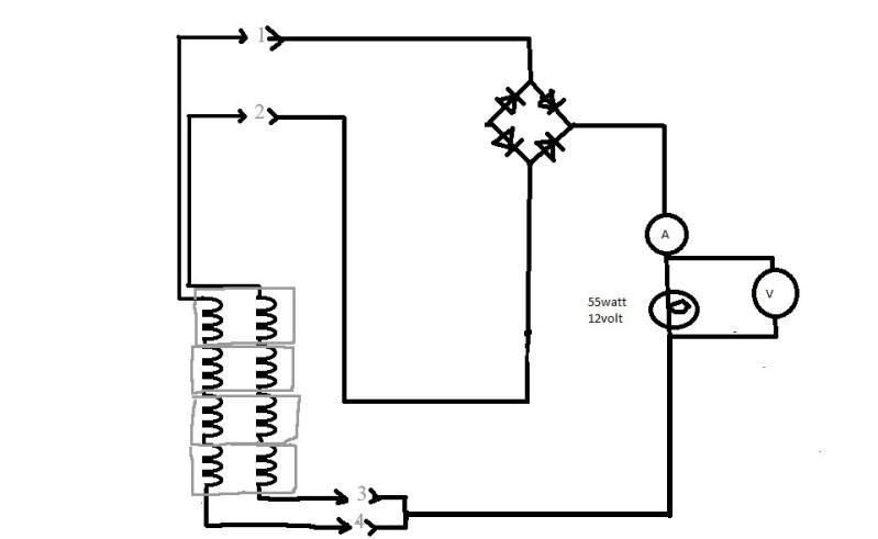
Bill
-
DewCatTea-Bob
- Posts: 2897
- Joined: Sun Nov 01, 2009 10:53 am
- Location: Near SE side of Lake Michigan
Dual Half-wave Rectification, no longer with Happy-effect
" Like this one but 1-4 and 2-3 is A/B and C/D; "
____ Okay Bill thanks ! _ I guess I can see why you called it "series/parallel" (but that makes for some confusion).
That's actually the old dual half-wave rectification arrangement, only now in combo with the 'straight-series' re-arrangement, (rather than Ducati's fore & back arrangement).
__ I'm glad that you-yourself thought to try-out this particular circuit-arrangement Bill, because while I certainly would've been interested in it's test-outcome, I wouldn't have wanted to be the one to push you into doing it.
__ Comparing this result-outcome to the previous equivalent version (with the stator-windings NOT in the straight-forward winding-fashion), should prove to be interesting.
I'll gather-up the two sets of results and post them all here for comparison within this same post, (down below).
__ Of particular interest (compared to most other testing), is the quite notable reduction of the working-impedance ! _ Apparently taking the 'AC' out of the picture entirely, greatly diminishes the working-impedance,, which of course certainly stands to reason (since AC & coil-windings really hate each other) !
And that allows the max.power (whatever amount it is), to become available at a working-impedance that's nearer in value to that of the max.working-load's resistance.
____ We already have lots of other test-results which still need to be (more directly) compared, (now more than ever) !
__ For direct comparison now, here follows both sets of Bill's dual half-wave testing,
with old/stock results (from page-24) listed first, followed by the results obtained with the stock stator-windings re-arranged into the 'straight' series configuration.
Dual half wave, ‘stock parallel’, 1ohm 3450rpm----6.6a, 21.6vac, 6.8vdc----44.9w
Dual half wave, ‘stock parallel’, 3ohm 3450rpm----3.6a, 28.9vac, 11.vdc----39.6w
Dual half wave, ‘stock parallel’, 5ohm 3450rpm----2.4a, 30.4vac, 12.vdc,---28.8w
3450rpm, series/parallel, A/B-C/D
1ohm----5.6a----5.8vdc----32.0w
2ohm----4.1a----8.5vdc----34.9w
3ohm----3.2a----9.9vdc----31.7w
4ohm----2.6a---10.7vdc----27.9w
5ohm----2.2a---11.2vdc----25.1w
6ohm----1.9a---11.6vdc----22.3w
__ Okay, we can now see the benefit for why Ducati didn't wind their stator's individual coil-windings in the more standard 'straight' fashion...
Comparing the outcome result-figures of the two (very separate) tests, we see that not only does Ducati's particular winding-arrangement provide for greater max.power-output, it also allows the max.power to be had along-with a very low working-impedance !
This confirms that the two stator-windings (as Ducati had them), were working in a complimentary fashion, and while there's no-doubt that some sort of official-name/term pre-exists for this particular 'happy-relationship', I've already referred to it as "Pull/Pull", (since the magnetic-fields of the rotor-magnets are of course already responsible for the 'Push' to get current flowing in the first place), and once that (pushed) current gets to flowing, it in turn begins establishing a magnetic-field of it's very-own (from the particular stator-winding which happens to be the one allowed to provide current-flow at the time),, and after that half-cycle of current-flow has peaked & begins falling-off, it's then fully-established magnetic-field also then falls, which induces a sort-of 'kick-start' current-flow into the OTHER stator-winding, having created a null of sorts which makes it somewhat easier for the rotor-magnets to begin THEIR job of 'pushing' current through the other stator-winding (which is the one next allowed to provide current-flow). _ Then next, that 'other stator-winding' performs the very same trick in return, for it's counterpart -(neighboring stator-winding), therefore each winding's collapsing-field helps to pull the other's next half-cycle into existence, (thus the 'pull/pull' concept),, with that 'effect' being equivalent to actual 'NEGATIVE working-impedance', (which is why I've used "Pull/Pull" instead of 'push/push' [as in the manor in which magnets 'push'] ).
__ Since the 'complementary-effect' effectively creates negative-impedance, (which cancels-out a portion of the standard working-impedance of the power-circuit), thus fortunately then allowing 'max.power' to become available at a lower overall working-impedance,, that then likewise allows for more efficient power-transfer to load-systems with extra-low total load-resistance /(same as extra-high total power-consumption).
(It's become clear that pretty-much most-all of the seemingly mysterious power-output deficiencies, were simply due to resulting higher 'working-impedance' values, of those other various power-circuits.)
__ On top of that, it seems that the 'complementary-effect' also must stretch-out the DC half-cycle from it's normal 180-degree life-span, to somewhere nearer 270-degrees long,,
thus accounting for the additional power, (now proven to not be available without the added complementary-effect).
The result of this (i pull u after u pull me, effect), is somewhat considerably better than mere 'full-wave', since full-wave half-cycles don't quite meet each other (due to nulls between them),, where-as the complimentary-effect actually causes the (normally 180-degree long) half-cycles to overlap (as much as 90-degrees).
__ I have now added pix to help see what the results of Ducati's complementary-effect might look like on an o.scope, (as seen in the lower pic).
____ The next obvious step for testing, is dual FULL-wave rectification (of both section-I & section-II, in parallel-fashion). _ Bill, do you have more than one FW.bridge-block ?
Hopeful-Cheers,
-Bob
You do not have the required permissions to view the files attached to this post.
PLEASE NOTE... If this-post is not-yet signed-off with '-Bob', then I'm still in the process of completing it,, and if not also included with 'DCT' near bottom as well, then I may edit this post's wording at a later time. - Dct.Bob
-
ecurbruce
- Posts: 317
- Joined: Fri Apr 01, 2011 12:43 am
- Location: Hurricane mills TN
Re: 6volt or 12 volt?
Bob says" I HAD assumed that Bruce had patterned his depicted-drawing on an actual stator-example he's had in his possession, BUT now, I have to ask you -(Bruce), is your drawing (with it's shown 24 lead-ends particularly connected to all the 24 terminal-points) directly based on your known-knowledge of the stator, OR, merely based on just logical-guesswork on your-part ?"
I would have to say this drawing is more a logical arrangement meant to incorporate Bill's drawing into mine, and best used to organize schematic drawings in a logical manner. Looking at my stator, this doesn't match exactly how the leads are arranged literally, so as to be able to copy exactly from the drawing to the stator. To wire the stator is still going to take some continuity testing just to see where everything is going, but to depict it in the drawing the way it really is would further confuse things (logically) for schematic drawings. Bill had noted that there was one spool that was backwards or reversed and depicted such in his drawing, and I left that detail the way he had it.
Here is a version of drawing depicting the seperate sections I think the way you described.
You do not have the required permissions to view the files attached to this post.
Return to “Ducati Singles Main Discussions (& How to Join)”
Who is online
Users browsing this forum: No registered users and 135 guests