I think the difference in ac to dc volts on each measurement here is not because of one being ac and one being DC, the alternator output is read in RMS so should be close to the same expected dc voltage. Bill's reading of 12vac at the output of the alternator is around 33 volts Peak to peak. And not being familiar with the Fluke's he is using, there is a good chance they are true RMS meters.
the difference is likely due to voltage drops across the two forward biased diodes conducting at any one time. though at one and a half volts each, they are a little higher than I'd expect, but there is no other losses in this simple circuit to consider. When we trace current through a circuit is it fairly common to think of a diode forward biased as a short and reverse biased as an open, but in truth you will see a voltage drop across a forward biased diode. typically .5 to 1 volt. And just to be clear. it is just a rectifier right, not a R/R? and also I'd like to know that the rectifier is not grounded in any way.
Thanks again Bill
Mike
n-c alternator modifications: discussion and testing
Moderator: ajleone
-
wcorey
- Posts: 323
- Joined: Sun Jan 31, 2010 1:50 am
- Location: MA USA
Re: 6volt or 12 volt?
Don't know where to start responding, as is typical for me I initially hastily cobbled a bunch of stuff together for some quick answers, then realized I should have been much more methodical once I got in deeper than expected and things started getting complicated.
I feel like erasing the whole thing to date and starting again 'clean'...
I've weeded out some suspect jumpers and I'll start using the same meter/same test leads for the same function, I was at first randomly swapping them around. I've assembled a collection of various load resistors, all 1 ohm and from 55 to 200 watts. I'll attempt to clean up the rats nest/mess enough to form a single layer of stuff so to snap some pics where wires can be followed within reason and such, it's easier to do that than keep describing things. I'll also try to clean up my hasty and inconsistent terminology in regards to circuit/connection descriptions, the new diagrams are a good step in that direction. Some other things planned today so won't get to it for a while....
Bill
-
MotoMike
- Posts: 487
- Joined: Wed Aug 04, 2010 3:40 am
Re: 6volt or 12 volt?
Bill
I don't think there is a problem with your setup from what I can tell. I appreciate your efforts. Also, since you've got the 200 watt resister in place, nothing is gained by swapping it out. from a calculation point of view it is the 1 ohm value that is important. 200 watts is just the rating that it can handle, so probably the best one to have in there since you have exceeded a 55 watt bulb's ability to cope. Just cause I've been perplexed by the series connection readings, don't mean there is fault with your setup. And since Bob has said that non tech types would expect the reading to be double, I sense enlightenment is in the wings.
I don't think there is a problem with your setup from what I can tell. I appreciate your efforts. Also, since you've got the 200 watt resister in place, nothing is gained by swapping it out. from a calculation point of view it is the 1 ohm value that is important. 200 watts is just the rating that it can handle, so probably the best one to have in there since you have exceeded a 55 watt bulb's ability to cope. Just cause I've been perplexed by the series connection readings, don't mean there is fault with your setup. And since Bob has said that non tech types would expect the reading to be double, I sense enlightenment is in the wings.
-
DewCatTea-Bob
- Posts: 2897
- Joined: Sun Nov 01, 2009 10:53 am
- Location: Near SE side of Lake Michigan
Diode Voltage-drops
By: MotoMike...
" And not being familiar with the Fluke's he is using, there is a good chance they are true RMS meters. ?
____ Mike, I'm sure Bill's chosen meter does AC-voltage in RMS but, couldn't it be that it's read-out is just off-cal on the high-side a bit "?
Whenever I questioned a meter's reading, I'd just compare it to another's, so as to be sure they're both correct.
" but in truth you will see a voltage drop across a forward biased diode. typically .5 to 1 volt. "
____ Mike, MY training taught to expect that diodes must drop
one-half volt, however it's actually .3 to .7 depending on type.
DCT-Bob
PLEASE NOTE... If this-post is not-yet signed-off with '-Bob', then I'm still in the process of completing it,, and if not also included with 'DCT' near bottom as well, then I may edit this post's wording at a later time. - Dct.Bob
-
DewCatTea-Bob
- Posts: 2897
- Joined: Sun Nov 01, 2009 10:53 am
- Location: Near SE side of Lake Michigan
Re: 6volt or 12 volt?
By: wcorey...
" I feel like erasing the whole thing to date and starting again 'clean'... "
____ Actually, it would be best to leave what you have here, as is (for now at least), and since this is such a top-notch thread-topic, it ought to have it's very-own dedicated thread ! _ If you agree, let me know, and I'll then get it started for us.
" I'll start using the same meter/same test leads for the same function, "
____ Before you choose your meter(s), it would be useful to first check them against one another's readout-readings, so as to make sure they're in agreement (thus still calibrated for accurate readings).
" I've assembled a collection of various load resistors, all 1 ohm and from 55 to 200 watts. "
____ The resistors with the highest wattage-ratings are simply most capable of handling the heat (without burning-up).
__ I am a bit concerned that your load is only "1" ohm, cuz if the load-resistance is too close to that of the alt.winding's own resistance, then the windings will have to handle excessive heat-dissipation, (and if the load-resistance is lower than that of the alt.winding, then the alt.winding itself will partially act as the load as well and that would be bad for getting useful readings).
So I'd suggest a load of 2 to 5 ohms,, and so if you could solidly connect a pair of your 1-ohm/55-watt resistors in series, then you'd have a suitable 2-ohm/110w load for your testing.
(Any comments on that Mike?)
" I'll also try to clean up my hasty and inconsistent terminology in regards to circuit/connection descriptions, "
____ That's a cool attitude Bill, and I'm sure Mike & I both will be glad to help you learn such !
" Some other things planned today so won't get to it for a while.... "
____ That's quit fine Bill, as we should be so grateful that you're doing even half as much as the rate you've been doing !
____ I think that since we've been getting such inconsistent results with full AC testing, that the FW-rectification should be switched for half-wave rectification...
That way AC can't have a chance to include it's otherwise possible (seemingly magic) effects into the circuit of your power-testing.
__ So after being sure that there's no leakage between the two alt.windings (by using an ohm-meter to make sure that resistance between the two windings is at least 10K-ohms), it would be good to know the 'half-wave' power-output of each stator-winding alone, and also with both in series... And also, there's two ways that the two stator-windings could be put in series - either head-to-tail/(tail-to-head), thus taking output from one head & one tail,, OR, head-to-head/(tail-to-tail), thus taking output from two heads (or two tails).
All that (seemingly unnecessary) testing may lead to otherwise unreachable conclusions.
__ To get the 'half-wave' output-power for testing, you can simply use your FW.bridge-block by ignoring it's AC-inputs, and simply wire-up your (series-type circuit) to it's Plus & Minus terminals, (which will incidentally maintain the two-diode voltage-drop, as before).
____ Mike, do you-yourself not see the possible usefulness of this suggested HALF-wave rectification test-work ?
____ Jumping way-ahead Bill, I gather it must be that you-yourself have a stake in this particular testing, perhaps because you're still considering using same stator in your project-Duke ? _ If so, and you're still not content with the power you can get from this four core-coil setup, will you then consider converting-over to six core-coils, as Bruce has done ? ...
I figure that since you realized you'd have to adapt the n-c stator to your w-c, that you would be intending to make an adapter-plate anyhow, (thus getting-around the situation which Bruce was faced with).
__ Did you also get a n-c rotor along-with that n-c stator you're testing ? _ If so, have you already determined that all will work okay for your on your w-c project ?
Hopeful-Cheers,
-Bob
PLEASE NOTE... If this-post is not-yet signed-off with '-Bob', then I'm still in the process of completing it,, and if not also included with 'DCT' near bottom as well, then I may edit this post's wording at a later time. - Dct.Bob
-
ecurbruce
- Posts: 317
- Joined: Fri Apr 01, 2011 12:43 am
- Location: Hurricane mills TN
Re: 6volt or 12 volt?
Bill,
Just for kicks, wire the circuit one more way... run the jumper between 1 and 3, and connect to the rectifier 2 and 4. It's still series,
Will it make a difference?
Bruce
(edit)
(Sorry, Bob, I think we were posting at the same time)
Just for kicks, wire the circuit one more way... run the jumper between 1 and 3, and connect to the rectifier 2 and 4. It's still series,
Will it make a difference?
Bruce
(edit)
(Sorry, Bob, I think we were posting at the same time)
-
DewCatTea-Bob
- Posts: 2897
- Joined: Sun Nov 01, 2009 10:53 am
- Location: Near SE side of Lake Michigan
In Consistant-series or Inconsistant-series
" run the jumper between 1 and 3, and connect to the rectifier 2 and 4. It's still series,
Will it make a difference? "
____ Perhaps both you & Bill had missed that I had already suspected that Bill may have already done so inadvertently (if all 4 of his wire-leads are the same color).
Fun-Cheers,
-Bob
Will it make a difference? "
____ Perhaps both you & Bill had missed that I had already suspected that Bill may have already done so inadvertently (if all 4 of his wire-leads are the same color).
Fun-Cheers,
-Bob
PLEASE NOTE... If this-post is not-yet signed-off with '-Bob', then I'm still in the process of completing it,, and if not also included with 'DCT' near bottom as well, then I may edit this post's wording at a later time. - Dct.Bob
-
ecurbruce
- Posts: 317
- Joined: Fri Apr 01, 2011 12:43 am
- Location: Hurricane mills TN
Re: 6volt or 12 volt?
yea, I saw that, I think that's what woke it up in my mind. I was just waiting to see if anyone else would carry it forward.
-
wcorey
- Posts: 323
- Joined: Sun Jan 31, 2010 1:50 am
- Location: MA USA
Re: 6volt or 12 volt?
Mmmm, just pan fried a couple brook trout that were swimming around a few hours ago.
Ok, I'm back and open for business, ready for duty as test mule. I for one would welcome a fresh thread to start again in, go for it at your discretion.
And no, Bob, I have nothing really at stake here, my motor already has an adapted Nippon Denso setup fitted, though I plan to swap a few around at some point (more to play with rotor weight differences than anything).
To adapt the n-c stator to w-c is more of a bother than it's worth at this point, I'd like to get a 6 coil w-c stator to play with though. It seems so far there is no difference or issues in fitment to the engine/crank between the n-c and w-c rotors.
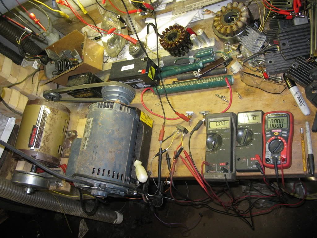
I'm putting up some pics so we can point to/refer to details more directly and descriptively, not so organized to be self explanatory but at least with consistently color coded wires on all but the meters.
I get .5 ohm across 1 and 3, .6 ohm across 2 and 4. No reading across 1and 2 or 3 and 4 (a meg ohm if I hold the leads on with my fingers ).
).
Here's the whole mickey mouse shootin' match:
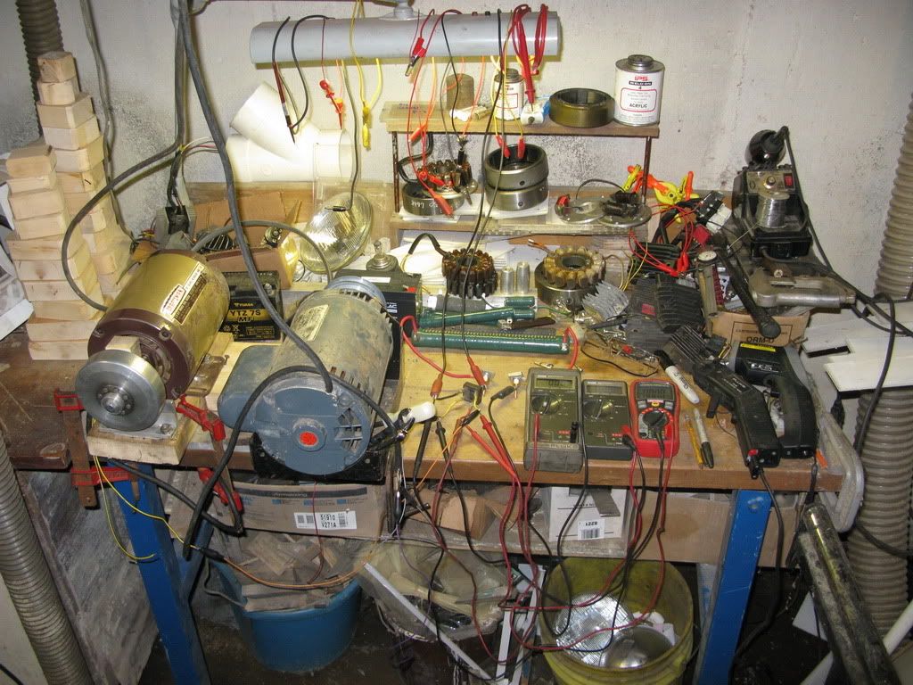
Here's how I get 6k rpm, for 3450 I remove the belt and use the smaller motor directly;
The two original wires from the stator (1 and 2) are the black cord , with a black and a white conductor.
The added wires (3 and 4) are the yellow ones (one has a black stripe). (all coming out of the alternator at 8 o'clock and draped over the grey motor)
The other end of the black wire (through it's set of coils) is yellow/black, the white wire has the plain yellow at it's other end.
(since 1,2,3 and 4 aren't color coded on the drawing, the two pairs are interchangeable in my descriptions)
The black wire has a purple jumper connection,
the white has a grey jumper,
the yellow has yellow
and the black/yellow has orange.
Bill
Ok, I'm back and open for business, ready for duty as test mule. I for one would welcome a fresh thread to start again in, go for it at your discretion.
And no, Bob, I have nothing really at stake here, my motor already has an adapted Nippon Denso setup fitted, though I plan to swap a few around at some point (more to play with rotor weight differences than anything).
To adapt the n-c stator to w-c is more of a bother than it's worth at this point, I'd like to get a 6 coil w-c stator to play with though. It seems so far there is no difference or issues in fitment to the engine/crank between the n-c and w-c rotors.
I'm putting up some pics so we can point to/refer to details more directly and descriptively, not so organized to be self explanatory but at least with consistently color coded wires on all but the meters.
I get .5 ohm across 1 and 3, .6 ohm across 2 and 4. No reading across 1and 2 or 3 and 4 (a meg ohm if I hold the leads on with my fingers
Here's the whole mickey mouse shootin' match:
Here's how I get 6k rpm, for 3450 I remove the belt and use the smaller motor directly;
The two original wires from the stator (1 and 2) are the black cord , with a black and a white conductor.
The added wires (3 and 4) are the yellow ones (one has a black stripe). (all coming out of the alternator at 8 o'clock and draped over the grey motor)
The other end of the black wire (through it's set of coils) is yellow/black, the white wire has the plain yellow at it's other end.
(since 1,2,3 and 4 aren't color coded on the drawing, the two pairs are interchangeable in my descriptions)
The black wire has a purple jumper connection,
the white has a grey jumper,
the yellow has yellow
and the black/yellow has orange.
Bill
Last edited by wcorey on Fri Jul 29, 2011 7:35 pm, edited 2 times in total.
-
wcorey
- Posts: 323
- Joined: Sun Jan 31, 2010 1:50 am
- Location: MA USA
Re: 6volt or 12 volt?
__ To get the 'half-wave' output-power for testing, you can simply use your FW.bridge-block by ignoring it's AC-inputs, and simply wire-up your (series-type circuit) to it's Plus & Minus terminals, (which will incidentally maintain the two-diode voltage-drop, as before).
I don't understand this... wouldn't you have to use one ac input on the rectifier?
__ I am a bit concerned that your load is only "1" watt,
You may want to correct that...
I have other large wattage resistors at 3, 5 and 100 ohms if needed.
These pics will give me an indication if my previous post was intelligible and yes, I'm playing games...
(<EDIT> No one noticed this and my game backfired on me so I'm adding the pertinent details to fill in the blanks that I had intended you all to figure out.)
<EDIT>Full wave, 'standard' series, 2ohm, 3450 rpm, 4.5a 12.7vac, 9.6vdc
<EDIT>
Just for kicks, wire the circuit one more way... run the jumper between 1 and 3, and connect to the rectifier 2 and 4. It's still series,
Will it make a difference?
<EDIT>Yes, it apparently makes ad difference, there was no output...
Bill
Last edited by wcorey on Fri Jul 29, 2011 6:47 pm, edited 5 times in total.
Return to “Ducati Singles Main Discussions (& How to Join)”
Who is online
Users browsing this forum: No registered users and 34 guests