Bob wrote:
I'd tend to doubt that a good meter that's made to read such high current amounts would not be calibrated so as to take it's-self into account.
MM
the meter producing inconsistent results here is the volt meter and it is just doing what it is supposed to do. the volt meter has no way of knowing what loads are in the circuit, just measuring what you are telling it to.
as to the amp meter, it depends on what you call good. The greatest majority of current meters use this resistor set up that I describe. there are other methods, but none as simple, reliable or inexpensive to produce.
The designers will typically refer to this resistor as a sensing resistor or a shunt. the way to make it have less effect on the readings, is to use a very small omhic value sense resistor so that the voltage drop across it is a very small part of the total. To use a very small resistor you must use metering circuits that have the very great sensitivity to read the small voltage drop across the very small (ohmic value) resistor. then the meter circuitry must be able to accurately distinguish very small differences and convert them to that appropriate current reading. The problem with reducing the omic value is that the voltage across it, that you are needing to examine will be smaller than the various voltage floating around in the air and being induced into the wires by magnetic fields produced by motors, lights, surrounding wiring and any number of spurious sources. So to have a meter that can make this small precise desired measurement and reject the other undesired spurious voltages being induced around it, requires shielding and engineering, and a lot of experimentation. So like so many things, you reach a point that is good enough for most your needs at a price point that is acceptable and recognize your limitations. I have seen a decent quality Fluke exhibit this trait.
I would consider a hand held Fluke brand multimeter to be a good meter.
n-c alternator modifications: discussion and testing
Moderator: ajleone
-
wcorey
- Posts: 323
- Joined: Sun Jan 31, 2010 1:50 am
- Location: MA USA
Re: 6volt or 12 volt?
Ok, round three, with a (beneficial) twist...
This is getting difficult to keep track of, if I omit answering any important questions please don't hesitate to reiterate.
Yes, doing the current across the bulb is easier and uses less jumpers, though I haven't gone back to figure out if it improves the consistency of readings.
I have added the ability to change the rpm's a bit by putting a pulley on the opposite end of the fixture motor and using another motor (just clamped to the bench) with a larger pulley to spin it. I'll have to watch the end of the unused motor plug . My first setup ended up yielding about 4100 rpm, I'll try to get it set up closer to 5k later.
I feel like I'm back in the lab, having to document procedures and equipment utilized
Meters are both a Fluke 77 and 73, as well as a mid grade Craftsman, none have been calibrated in many years, though the Craftstman is relatively new. I've been rounding the numbers to one decimal point, if it makes a difference, I can go one more place. Past that I'll need to set up an o'scope...
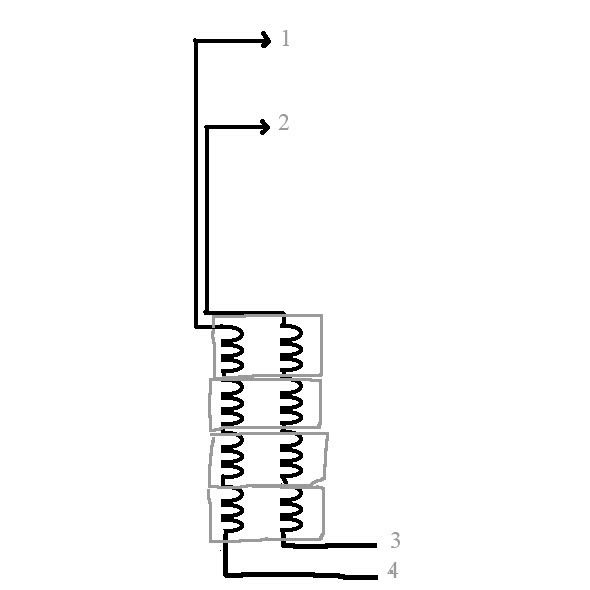
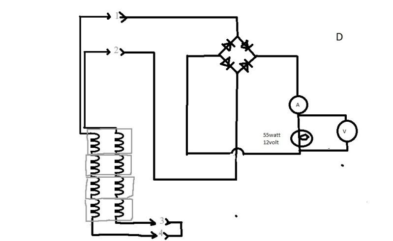
I did a quick 'n dirty edit of Mikes schematic, the concept is so basic I really don't feel it's needed but if it helps to keep things clear I figured it might have been worth the bother. Mike, I'm still not clear on what aspect of the testing connection descriptions are too vague to decipher...
I left it drawn 'unconnected' with the possible connections numbered only so as to be able to use it as a reference when trying to explain things. The grey boxes denote stator cores where the two separate windings share a common core.
Here's the meat and potatoes, raw data. I wanna see some conclusions and/or correlations at some point here, I'm more than certain Bob already has many he's holding out reporting on...
3450 rpm, AC output from one 'set' of coils (either 1 and 4 or 2 and 3) to a generic rectifier block, then from the block to the (55w headlight) load. Current taken across load, volt readings taken at rectifier.
3.2a, 13.5vac, 10.4vdc
Same configuration taken at (revised from 4250) 4100 rpm;
4.2a, 15.6vac, 12.2vdc
As expected, readings taken from the 'series' setup stator (3 and 4 jumpered together, outputs from 1and 2) are similar;
3450rpm
3.5a, 13.7vac, 10.5vdc
Should I then try grounding 3 and 4 to the stator plate and connect that to the rectifier neg? I still don't quite grasp the result that whole concept. Less voltage, more current?
Put a cone pulley on the 'overdrive' motor, which should yield 4310, 4830, 5450 and 6000 rpm's, from which would you'all like readings from next...
More to come but... It just got sunny outside for the first time in days, I'm going fishing.
Bill
This is getting difficult to keep track of, if I omit answering any important questions please don't hesitate to reiterate.
Yes, doing the current across the bulb is easier and uses less jumpers, though I haven't gone back to figure out if it improves the consistency of readings.
I have added the ability to change the rpm's a bit by putting a pulley on the opposite end of the fixture motor and using another motor (just clamped to the bench) with a larger pulley to spin it. I'll have to watch the end of the unused motor plug
...as to the amp meter, it depends on what you call good.
I feel like I'm back in the lab, having to document procedures and equipment utilized
Meters are both a Fluke 77 and 73, as well as a mid grade Craftsman, none have been calibrated in many years, though the Craftstman is relatively new. I've been rounding the numbers to one decimal point, if it makes a difference, I can go one more place. Past that I'll need to set up an o'scope...
I did a quick 'n dirty edit of Mikes schematic, the concept is so basic I really don't feel it's needed but if it helps to keep things clear I figured it might have been worth the bother. Mike, I'm still not clear on what aspect of the testing connection descriptions are too vague to decipher...
I left it drawn 'unconnected' with the possible connections numbered only so as to be able to use it as a reference when trying to explain things. The grey boxes denote stator cores where the two separate windings share a common core.
Here's the meat and potatoes, raw data. I wanna see some conclusions and/or correlations at some point here, I'm more than certain Bob already has many he's holding out reporting on...
3450 rpm, AC output from one 'set' of coils (either 1 and 4 or 2 and 3) to a generic rectifier block, then from the block to the (55w headlight) load. Current taken across load, volt readings taken at rectifier.
3.2a, 13.5vac, 10.4vdc
Same configuration taken at (revised from 4250) 4100 rpm;
4.2a, 15.6vac, 12.2vdc
As expected, readings taken from the 'series' setup stator (3 and 4 jumpered together, outputs from 1and 2) are similar;
3450rpm
3.5a, 13.7vac, 10.5vdc
Should I then try grounding 3 and 4 to the stator plate and connect that to the rectifier neg? I still don't quite grasp the result that whole concept. Less voltage, more current?
Put a cone pulley on the 'overdrive' motor, which should yield 4310, 4830, 5450 and 6000 rpm's, from which would you'all like readings from next...
More to come but... It just got sunny outside for the first time in days, I'm going fishing.
Bill
-
MotoMike
- Posts: 487
- Joined: Wed Aug 04, 2010 3:40 am
Re: 6volt or 12 volt?
probably just a way of speaking but current needs to be taken in series with the load, not across it.
and again. thanks much for all the work you are doing.
Mike
and again. thanks much for all the work you are doing.
Mike
-
MotoMike
- Posts: 487
- Joined: Wed Aug 04, 2010 3:40 am
Re: 6volt or 12 volt?
High Bill
Bill wrote:
As expected, readings taken from the 'series' setup stator (3 and 4 jumpered together, outputs from 1and 2) are similar;
3450rpm
3.5a, 13.7vac, 10.5vdc
MM
This is the reading that was not expected by me. putting those two sets of stator coils in series I was expecting the voltage across them to double. I'm scratching my head as to why and how it could be essentially the same.
where are you at Bill?
Mike
-
wcorey
- Posts: 323
- Joined: Sun Jan 31, 2010 1:50 am
- Location: MA USA
Re: 6volt or 12 volt?
I'm back...
You and me both, the only reason I said "expected" here is because I had already seen similar results in the previous setups and also one reason I had said I too was head scratching. Maybe something to do with the direction in which they're wound and/or that the series setup is not how it's implemented in the stock application (as the 'middle' is grounded).
Bob knows, as is his typical mo, he's holding out on us. I'm awaiting enlightenment...
Now I can't remember how the hell I had it, I know I got consistent readings. I'll figure it out on my next attempt, I'm (kind of relatively) excited I get to run it at 6k rpm...
Bill
This is the reading that was not expected by me. putting those two sets of stator coils in series I was expecting the voltage across them to double. I'm scratching my head as to why and how it could be essentially the same.
You and me both, the only reason I said "expected" here is because I had already seen similar results in the previous setups and also one reason I had said I too was head scratching. Maybe something to do with the direction in which they're wound and/or that the series setup is not how it's implemented in the stock application (as the 'middle' is grounded).
Bob knows, as is his typical mo, he's holding out on us. I'm awaiting enlightenment...
probably just a way of speaking but current needs to be taken in series with the load, not across it.
Now I can't remember how the hell I had it, I know I got consistent readings. I'll figure it out on my next attempt, I'm (kind of relatively) excited I get to run it at 6k rpm...
Bill
-
MotoMike
- Posts: 487
- Joined: Wed Aug 04, 2010 3:40 am
Re: 6volt or 12 volt?
Bill
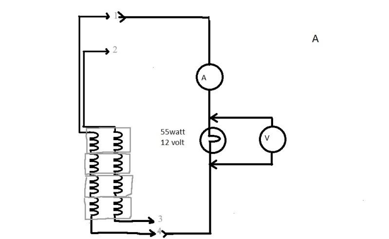
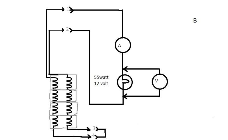
thanks for the drawing. I have reworked it yet again. I think it would probably be fine to test it at your initial rpm. and do all the configuration changes and checks with it at this intermediate rpm. Let me know if the following schematics labled A,B,C and D are the way you have connected the circuits. then we can go on and see what we have. As it pertains to checking the alternator output I think circuits A and B would be the way to go. after initial tests, you can put more bulbs in parallel with the original or use smaller or larger wattage rating bulbs to see if the alternator can handle it.
kind regards,
Mike
-
wcorey
- Posts: 323
- Joined: Sun Jan 31, 2010 1:50 am
- Location: MA USA
Re: 6volt or 12 volt?
Yes, those drawings are correct. I've already provided data based on every one of the above drawings, as well as the addition of simultaneous vac readings with the vdc on the rectified circuits. If you need clarification as to what data correlates to what drawing, just point it out.
The variation in output at different rpm can provide insight into the relative wattage rating.
Ok, round four...
6k rpm fried my last expendable headlight.
Forget about the current readings on the past data, the meters battery was weak and the readings are suspect.
New data;
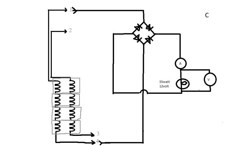
3450 rpm, load = 1ohm, 200w resistor, wired as per mikes drawing C; 6.5a, 9.8vac, 7.1vdc
6000 rpm, load = 1ohm, 200w resistor, wired as per mikes drawing C; 8.4a, 12.2vac, 9.2vdc
3450 rpm, load = 1ohm, 200w resistor, wired as per mikes drawing D; 4.9a, 7.9vac, 5.4vdc
Bill
The variation in output at different rpm can provide insight into the relative wattage rating.
Ok, round four...
6k rpm fried my last expendable headlight.
Forget about the current readings on the past data, the meters battery was weak and the readings are suspect.
New data;
3450 rpm, load = 1ohm, 200w resistor, wired as per mikes drawing C; 6.5a, 9.8vac, 7.1vdc
6000 rpm, load = 1ohm, 200w resistor, wired as per mikes drawing C; 8.4a, 12.2vac, 9.2vdc
3450 rpm, load = 1ohm, 200w resistor, wired as per mikes drawing D; 4.9a, 7.9vac, 5.4vdc
Bill
-
DewCatTea-Bob
- Posts: 2897
- Joined: Sun Nov 01, 2009 10:53 am
- Location: Near SE side of Lake Michigan
Re: 6volt or 12 volt?
wcorey wrote:Ok, round three, with a (beneficial) twist...
This is getting difficult to keep track of, if I omit answering any important questions please don't hesitate to reiterate.
Yes, doing the current across the bulb is easier and uses less jumpers, though I haven't gone back to figure out if it improves the consistency of readings.
I have added the ability to change the rpm's a bit by putting a pulley on the opposite end of the fixture motor and using another motor (just clamped to the bench) with a larger pulley to spin it. I'll have to watch the end of the unused motor plug...as to the amp meter, it depends on what you call good.
I feel like I'm back in the lab, having to document procedures and equipment utilized
Meters are both a Fluke 77 and 73, as well as a mid grade Craftsman, none have been calibrated in many years, though the Craftstman is relatively new. I've been rounding the numbers to one decimal point, if it makes a difference, I can go one more place. Past that I'll need to set up an o'scope...
I did a quick 'n dirty edit of Mikes schematic, the concept is so basic I really don't feel it's needed but if it helps to keep things clear I figured it might have been worth the bother. Mike, I'm still not clear on what aspect of the testing connection descriptions are too vague to decipher...
I left it drawn 'unconnected' with the possible connections numbered only so as to be able to use it as a reference when trying to explain things. The grey boxes denote stator cores where the two separate windings share a common core.
Here's the meat and potatoes, raw data. I wanna see some conclusions and/or correlations at some point here, I'm more than certain Bob already has many he's holding out reporting on...
3450 rpm, AC output from one 'set' of coils (either 1 and 4 or 2 and 3) to a generic rectifier block, then from the block to the (55w headlight) load. Current taken across load, volt readings taken at rectifier.
3.2a, 13.5vac, 10.4vdc
Same configuration taken at (revised from 4250) 4100 rpm;
4.2a, 15.6vac, 12.2vdc
As expected, readings taken from the 'series' setup stator (3 and 4 jumpered together, outputs from 1and 2) are similar;
3450rpm
3.5a, 13.7vac, 10.5vdc
Should I then try grounding 3 and 4 to the stator plate and connect that to the rectifier neg? I still don't quite grasp the result that whole concept. Less voltage, more current?
Put a cone pulley on the 'overdrive' motor, which should yield 4310, 4830, 5450 and 6000 rpm's, from which would you'all like readings from next...
More to come but... It just got sunny outside for the first time in days, I'm going fishing.
Bill
" Ok, round three, with a (beneficial) twist..."
____ Very good posting Bill ! _ Although I'm not sure I picked-up on the (happy?) "twist" .
" Yes, doing the current across the bulb is easier and uses less jumpers, though I haven't gone back to figure out if it improves the consistency of readings. "
____ Not sure what you're meaning here.
'Voltage' (not "current") is measured "across" the load.bulb, while current is measured 'through' the circuit & bulb.
" I have added the ability to change the rpm's a bit by putting a pulley on the opposite end of the fixture motor and using another motor (just clamped to the bench) with a larger pulley to spin it. I'll have to watch the end of the unused motor plug "
____ I'm not getting a good picture in my mind of your exact setup there... Got any pix of it we can see ?
.
" Meters are both a Fluke 77 and 73, as well as a mid grade Craftsman, none have been calibrated in many years, though the Craftstman is relatively new. "
____ If you connect two (or all 3) amp-meters in series and their readings all agree (as to the amount of current passing-through), you then ought to be able to assume that they're still properly calabrated.
" Here's the meat and potatoes, raw data. I wanna see some conclusions and/or correlations at some point here, I'm more than certain Bob already has many he's holding out reporting on... "
____ I'll try to answer specific questions, if ya ask any.
" 3450 rpm, AC output from one 'set' of coils (either 1 and 4 or 2 and 3) to a generic rectifier block, then from the block to the (55w headlight) load. Current taken across load, volt readings taken at rectifier. "
____ It ought be noted that the current-reading need not be taken "across" (actually 'through') the load, as the current has to be the very-same through-out the entire (series) circuit ! _ So taking the ampre-reading as it leaves or enters the rectifier is just as useful !
" 3.2a, 13.5vac, 10.4vdc
Same configuration taken at (revised from 4250) 4100 rpm;
4.2a, 15.6vac, 12.2vdc "
____ Fairly impressive results (from what should be only "half" of the alternator) at under 3500-RPM.
__ Note that the AC-voltage (input into the FW-rect.block) is 3.4-volts greater than the DC-voltage (output from the rect.block)... This is suspect as the loss should only be just 1.4-volts -(.7v per diode) !
" readings taken from the 'series' setup stator (3 and 4 jumpered together, outputs from 1and 2) are similar;
3450rpm
3.5a, 13.7vac, 10.5vdc "
____ That's only .3-amp & .1-volt (thus merely .03-watt) increase !
Most (non-tech types) would expect these (in 'series' power-sources arrangement) figures to become doubled (from that of a single power-souce alone).
" Should I then try grounding 3 and 4 to the stator plate and connect that to the rectifier neg? "
____ NO, cuz not only would it make no diffrence if the stator-plate became electrically-envolved, (since it's been removed from any ground-circuit), but also doing that would create a short-circuit which would waste the output of one-half of the entire/series power-source (at the expence of overheating two of the bridge's diodes) !
" I still don't quite grasp the result that whole concept. Less voltage, more current? "
____ I'm not exactly sure of what you actually mean for sure, but when it comes to such AC power-sources, many relatively strange aspects can alter otherwase straight-forward logic (compared to ordinary straight-line DC).
" Put a cone pulley on the 'overdrive' motor, which should yield 4310, 4830, 5450 and 6000 rpm's, from which would you'all like readings from next... "
____ That's easy! - The highest you can (simply) acheive. _ Cuz with two such points established, we can then plot/calculate the rest (of possible RPM/output figures).
PLEASE NOTE... If this-post is not-yet signed-off with '-Bob', then I'm still in the process of completing it,, and if not also included with 'DCT' near bottom as well, then I may edit this post's wording at a later time. - Dct.Bob
-
DewCatTea-Bob
- Posts: 2897
- Joined: Sun Nov 01, 2009 10:53 am
- Location: Near SE side of Lake Michigan
Proper Amp.meter Connection !
wcorey wrote:MotoMike wrote:probably just a way of speaking but current needs to be taken in series with the load, not across it.
Now I can't remember how the hell I had it, I know I got consistent readings.
____ If you had your amp-meter connected like a volt-meter, then the bulb would not have lite-up (much), as the amp-meter would then have been as a short-circuit (in parallel with the bulb),, so you would've been tipped-off (that something was not right) when the light would've been extremely dim.
Fine-Cheers,
-Bob
PLEASE NOTE... If this-post is not-yet signed-off with '-Bob', then I'm still in the process of completing it,, and if not also included with 'DCT' near bottom as well, then I may edit this post's wording at a later time. - Dct.Bob
-
DewCatTea-Bob
- Posts: 2897
- Joined: Sun Nov 01, 2009 10:53 am
- Location: Near SE side of Lake Michigan
Bill's "round four" Results (with 1-ohm resistor-load)
By: wcorey...
" Ok, round four...
Forget about the current readings on the past data, the meters battery was weak and the readings are suspect. "
____ I don't think so Bill, as the battery in such meters is only needed for providing the ohm-meter readings (and possibly the meter's digital read-out brightness/clarity).
" New data;
3450 rpm, load = 1ohm, 200w resistor, wired as per mikes drawing C; 6.5a, 9.8vac, 7.1vdc
6000 rpm, load = 1ohm, 200w resistor, wired as per mikes drawing C; 8.4a, 12.2vac, 9.2vdc "
____ So at the lower RPM, a single alt.winding provides about 64-watts of AC-power and about 46-watts in DC-power.
While at the higher RPM, the single alt.winding provides about 102-watts of AC-power and about 77-watts in DC-power.
" 3450 rpm, load = 1ohm, 200w resistor, wired as per mikes drawing D; 4.9a, 7.9vac, 5.4vdc "
____ And at the lower RPM with BOTH alt.windings (connected in series-fashion), the power-output is then about 39-watts of AC-power and about 26.5-watts of DC-power.
__ Now we have two main thoughts to ponder (since THIS "New data" doesn't directly correlate with your previous-data)...
One thought is that your new 'load' (vs. the bulb) is reflecting different current-flow characteristics,
another is you may've mistakenly connected #2 to #4 (instead of #3 to #4, as before), or simply miss-referenced Mike's 'C' & 'D' drawings. (?)
Do you have all-4 of your wire-leads all the same color (so that such a mix-up is more likely) ?
____ I sure hope you're okay with all the testing Bill, cuz more needs to be done ! _ So are you prepared for what's next (after your current/present figures are checked) ?
Thanks a lot Bill !
Hopeful-Cheers,
-Bob
PLEASE NOTE... If this-post is not-yet signed-off with '-Bob', then I'm still in the process of completing it,, and if not also included with 'DCT' near bottom as well, then I may edit this post's wording at a later time. - Dct.Bob
Return to “Ducati Singles Main Discussions (& How to Join)”
Who is online
Users browsing this forum: No registered users and 22 guests