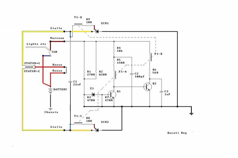
____ I've decided to post HERE my redone-version of the schematic-diagram (of Ducati's electronic-regulator), which MotoMike had first posted on this w.site in another thread.
Besides being properly -(stock like) colorized, I've also made some other changes so that it's colored wire-lines better reflect the actual wiring-scheme of the wide-case style wiring-layout.
__ If anyone sees any other possible improvements that could be made to this drawing-version, then please point them out, so that I might possibly add them into a further updated version. - (UPDATE: I-myself have since done so, and so have now further improved the scheme so as to better represent the real-world wire-line connections of the actual w-c physical wiring-layout.)
____ Mike, if you'd like to post your write-up on the workings of the regulator-circuit, then this thread is the best place to put it, (unless you have any reason to believe that it deserves it's very-own dedicated-thread).
Fun-Cheers,
-Bob
Stock WideCase Charging-system & Rect.Regulator Schematic
Moderator: ajleone
-
DewCatTea-Bob
- Posts: 2897
- Joined: Sun Nov 01, 2009 10:53 am
- Location: Near SE side of Lake Michigan
Stock WideCase Charging-system & Rect.Regulator Schematic
You do not have the required permissions to view the files attached to this post.
PLEASE NOTE... If this-post is not-yet signed-off with '-Bob', then I'm still in the process of completing it,, and if not also included with 'DCT' near bottom as well, then I may edit this post's wording at a later time. - Dct.Bob
-
MotoMike
- Posts: 487
- Joined: Wed Aug 04, 2010 3:40 am
Re: Stock WideCase Charging-system & Rect.Regulator Schemati
Bob
I'll post it here. I have it completed, but have run into a disagreement with my uncle as to the proper workings of T1. I don't think they are significant as we both agree it provides the gate, but I'd like to get it sorted before posting.
I wonder if the schematic in question was from someone reverse engineering it or if it was translated into english from an Italian source. I notice some non standard ways of rating components.
Mike
-
DewCatTea-Bob
- Posts: 2897
- Joined: Sun Nov 01, 2009 10:53 am
- Location: Near SE side of Lake Michigan
Re: Stock WideCase Charging-system & Rect.Regulator Schemati
" I'll post it here. "
____ I think that will be fine.
" I have it completed, but have run into a disagreement with my uncle as to the proper workings of T1. I don't think they are significant as we both agree it provides the gate, "
____ I believe that you must actually mean that T1 conveys the main-circuit's provided signal which helps to set the gate-bias. (?)
__ So have you both considered & taken into account the unique ("pull/pull")- co-assisting effect provided by the synergisticly-wound DUAL-alt.windings over all the stator-poles ?
I'm thinking that T1's end-result is likely influenced by the fact that the more power that's consumed by the load-system, the greater then is the extra-added induced-current into each stator-winding directly from the other,, thus providing some additional (somewhat hidden) effect on exactly how C1's effect combines with T1's (battery voltage-level supplied) effect, to ultimately control the gate. - (Just a thought that may help to break-off your disagreement.)
Let me know if any elaboration is desired concerning the pull/pull-effect of the dual-windings.)
" I wonder if the schematic in question was from someone reverse engineering it or if it was translated into english from an Italian source. "
____ Seems to have been done by a user of Italian-wording but, I doubt that it was done by Ducati, as the professional-level of the drawing (of a supposed Ducati-scheme) is somewhat substandard.
(I've now also posted the original-drawing in my post, so that my [real-world] changes to it can be easier noticed.)
__ On the other hand, I'm somewhat doubtful that it was reversed-engineered from an actual internal circuit-block, cuz unless there's some solvent that can melt-away the block's encasement-material, it's otherwise next to impossible to determine exactly what it's embedded component-items actually are.
____ So maybe perhaps the schematic is somewhat questionable as to it's trustworthy/actual authenticity.
I know if I-myself had created it, it then would've depicted T1 as a single-icon, so that it's currently-depicted 'A/B/C/D' sections' actual physical-relationship would be real-world arranged, (as I've done with the depicted alt.stator-windings).
Hopeful-Cheers,
-Bob
PLEASE NOTE... If this-post is not-yet signed-off with '-Bob', then I'm still in the process of completing it,, and if not also included with 'DCT' near bottom as well, then I may edit this post's wording at a later time. - Dct.Bob
-
MotoMike
- Posts: 487
- Joined: Wed Aug 04, 2010 3:40 am
Re: Stock WideCase Charging-system & Rect.Regulator Schemati
Inserted-note by DCT-Bob wrote:Mike, I'd like to delete this post which you've left blank...
If you object to that notion, then please leave a note here asap.
Thanks,
-Bob
Last edited by MotoMike on Thu Sep 22, 2011 2:57 pm, edited 1 time in total.
-
MotoMike
- Posts: 487
- Joined: Wed Aug 04, 2010 3:40 am
Re: Stock WideCase Charging-system & Rect.Regulator Schemati
Bob thanks for the color work.
I know there was some talk of the push pull effect of the alternator windings, and we did not really flesh that out. But no mater, the output of the alternator is the output of the alternator and the rectifier/regulator doesn’t care how it got to be what it is. I don’t think the function of C1 is critical and suspect it is there to eliminate transients and prevent false gates to the SCRs when they are not desired.
First lets just make it work as a rectifier. Consider that if the SCR’s were always gated, or simply acting as rectifying diodes, it will work as follows: During the half cycle when the left side of stator 1 is most negative the right side of stator 1 is more positive the left side of stator 2 will be most positive. Current will flow from the left side of stator 1 through SCR1 (virtual diode 1) all the way around, though the battery to the right side of stator 1. During that half cycle, the left side of stator 2 is most positive so SCR2 (virtual diode 2) is reverse biased and no path for current through it will exist. If we use the old D cell analogy to describe stator 1 for the snap shot of time described above, you would see that you have two batteries in parallel just as you would when jump starting a battery. In this circumstance when Stator 1 voltage exceeds battery voltage, the battery will charge. When the next half cycle comes around polarities across the stators will change with the left side of stator 2 going most negative and the left side of stator one going most positive. Current will flow then through SCR 2 (VD2) to the battery and to the right side of stator 2. SCR 1(VD1) is reverse biased and turned off. Only when voltage across the stators, in turn exceeds that of the battery voltage will the battery charge. To prevent overcharging we must be able to turn off the SCR’s when the battery is charged.
After much consideration and discussion with my uncle, an old time super tech whose forgotten more than I’ll ever know (don’t tell him I said so), I’ve come to this conclusion on how the circuit works. Included in the write up are some basics on how these components work.
For an SCR to conduct you need a positive on the anode (the right side of the SCR’s in the schematic) a negative on the cathode (left side of SCR’s) and a positive on the gate. These potentials can’t exist on these SCR’s solely from AC provided by the alternator, as when one of the SCRs is forward biased, a negative potential is present at the cathode and this negative is tied to the gate.
Q2 is an oscillator. left on its own, it would be an astable multivibrator, constantly changing back and forth from on to off. Assuming battery voltage is low and you want to gate the SCRs, when you first turn on the circuit you will see a large positive voltage at the base of Q2. Since both transistors are NPN they require positive on the Collector(top element) negative at the emitter(arrow element) and positive on the base (middle element) with respect to the emitter. These conditions exist as described in this paragraph above. Q2 will begin conducting emitter to collector and through T1B. T1 has 4 windings wound on a common core. in this configuration T1B is the primary with T1,A,C and D are the secondaries. When Q2 conducts current through T1B will create a field which will induce a voltage across T1A that is out of phase with battery voltage resulting in a negative seen at T1A bottom and at the base of Q2 causing it to shut off. When Q2 shuts off the field in T1B collapses and induces a voltage across T1A opposite of what it did initially placing a positive on the base of Q2 which turns Q2 back on which starts the cycle over. The purpose of all this is to also induce voltages across T1C and T1D which put a positive gate on both SCRs at the same time. In this state the SCRs would be gated many times per cycle and essentially act like the virtual diodes described in paragraph 2 above. How do we stop the gates?
Z1 is s critical part of the circuit and is chosen in this case to control Q1. It’s value is such that it is barely in it’s breakdown region when battery voltage is just above the voltage the engineers chose to begin battery charging. Any battery voltage above this will cause the Zener to conduct and any voltage below this will cause it to cut off. When Z1 fires or conducts, current flows through R7 and a positive voltage is developed across it. This positive voltage is seen at the top of R7and the base of Q1. Remembering conduction requirements for an NPN transistor, this will cause Q1 to conduct acting like a closed switch for the EC path causing a near ground value to be seen at the top of Q1. This very low voltage is seen at the base of Q2 and causes it to shut off. Q2 cannot come on again until Q1 turns off and that won’t happen until battery voltage falls to the point that Z1cuts off. When Z1 does cut off Q1 again acts as an open switch in the EC path and a positive voltage is again seen at its collector and at the base of Q2 allowing Q2 it to again commence oscillations and provide gates to the SCR’s.
That’s about it.
Thanks for reading.
Mike
-
DewCatTea-Bob
- Posts: 2897
- Joined: Sun Nov 01, 2009 10:53 am
- Location: Near SE side of Lake Michigan
Added-effect of Pull/pull-process on Rect.Regulator circuit
____ I've put-off responding here cuz my intended post-content would require more time than I can get in order to finish it all at once, however I've now come to realize that if I don't get started on it, then I may never get-around to posting anything at all here.
By: MotoMike...
" I know there was some talk of the push pull effect of the alternator windings, and we did not really flesh that out. "
____ Well "push pull" is a more common term occasionally used by electronic-techs to describe an action of some electronic-circuits, and doesn't represent exactly the same effect as that which I'm referring-to with the fairly unique winding-style of the Ducati 6-pole stators.
I've been using "Pull/Pull" because the alt.rotor obviously has been doing the main 'pushing' which began the whole process of flux-creation going, in the first-place,, so that's why I haven't been using 'push/push' (as well), which would otherwise be just about as applicable as 'pull/pull' to describe the extra/added-process (of flux-building/collapsing), but I wished to avoid any possible confusion (with the original/initial 'pushing' process done by the rotor). _ I'm sure there's probably an actual tech.name for the extra/added P/P-process, but I'm not recalling it and IT may not be as self-explanatory anyway.
" But no mater, the output of the alternator is the output of the alternator and the rectifier/regulator doesn’t care how it got to be what it is. "
____ Well that notion would make everything nice & simple if indeed exactly true, (depending on the actual workings of the regulator-circuits in conjunction with Ducati's particular alt.windings).
I realize that there's great temptation to look at the two separate alt.stator-windings as if they were same as simply a standard-wound single center-tapped -(transformer like) continuously-wound alt.winding, (as rather depicted in the ORIGINAL-drawing, [which I've (more-correctly) altered within my-own version]). _ However that arrangement-conception is not the actual real-world case ! _ (If it were, then neither alt.winding could pass it's built-up flux-field onto the other ! ... )
The relationship between the two alt.stator-windings is not similar as merely ONE continuous-winding like that of the primary-winding in an ign.coil,, but rather, their relationship is more like that of the primary & secondary windings of an ign.coil, EXCEPT that the turns-ratio is just 1:1 and BOTH windings take turns exciting each other, (instead of just the primary exciting the secondary, only) !
" I don’t think the function of C1 is critical and suspect it is there to eliminate transients and prevent false gates to the SCRs when they are not desired. "
____ I'm thinking that the action of C1 must be more complex than that expected, since the pull/pull-effect does-not increase the alt.power by increasing the alt.output-waveform's amplitude, but rather, increases the DURATION of the waveform, (due to the pull/pull-effect's action) !
So when the alt.windings are not passing current, the otherwise expected waveform (allowed by the rectification) would look as-if simply two normal 180-degree out-of-phase DC-pulses,, however, when the alt.windings do have current flowing through them, then each otherwise 180-degree long DC-pulse is width-expanded out to 270-degrees in duration, thus then putting an (otherwise unexpected) EXTRA 90-degrees (x2) of power-signal across C1. _ And that extra/added signal can't help but have some additional-effect on the charge-status of C1 (besides the influence of the AC signal-halves which are ignored by the HALF-wave rectifier setup).
" That’s about it. "
____ It would have been more helpful if you had included examples of cause & effect conditions. ...
We're led to expect that the regulator's rectifier-circuit is left shut-down when the battery's voltage is too low to activate the reg.circuitry, and that it also shuts-down whenever the battery/system-voltage reaches a high-enough level,, yet then when the power-load is increased against the system's presently-available power (like when the lights become turned-on), the regulator-circuitry must then become reset to allow more of the (previously unneeded)- stand-by power into the system, (otherwise, the system-voltage would slowly fall-downward until the battery lost a fair-bit of it's full-charge whilst the charging-system is left completely dormant for a relatively extended time-period).
__ So examples of such conditions and how the reg.circuitry responds, would be nice to go along with that which you've already included in your write-up.
____ I may likely add more wording to that which I already have here so far, later. -
-UPDATE... Instead, I've placed my expected additional-wording (which I HAD been thinking of adding to this post), within my Sept.25th-post (further-on in this thread).
Content-Cheers,
-Bob
PLEASE NOTE... If this-post is not-yet signed-off with '-Bob', then I'm still in the process of completing it,, and if not also included with 'DCT' near bottom as well, then I may edit this post's wording at a later time. - Dct.Bob
-
MotoMike
- Posts: 487
- Joined: Wed Aug 04, 2010 3:40 am
Re: Stock WideCase Charging-system & Rect.Regulator Schemati
Well bob, you are certainly welcome to write an alternate theory.
I'm not saying the push pull effect as you describe it does not exist, but the output of the alternator will still be an ac wave form and the rectifier regulator won't care how it got to be what it is.
Looking at the value of C1 I still think it is to eliminate transients and short ones at that.
all the conditions you describe may not be as well dealt with in this circuit as some of the more intelligent RRs do now but I don't see anything that would have the depicted RR gauging load quality. anything that drops the battery voltage enough to cut off Z1 will cause charging to take place.
Since its regulation function is determined by the function of Z1 it comes down to what voltage is available across the battery and nothing else. If it were a short duration load, it might only gate the scrs for a few cycles. If Q1 clamps Q2 due to adequate battery voltage no gates are produced, and no charging takes place. When battery voltage drops enough Q1 will cut off. and that will turn on Q2 and gates will again be produced.
Mike
-
DewCatTea-Bob
- Posts: 2897
- Joined: Sun Nov 01, 2009 10:53 am
- Location: Near SE side of Lake Michigan
Re: Stock WideCase Charging-system & Rect.Regulator Schemati
" you are certainly welcome to write an alternate theory. "
____ I haven't meant to imply your write-up is faulty Mike, and the old reg.circuit probably actually isn't sophisticated enough to sense when the amplitude of the half-cycle's extra-duration is increased.
" Looking at the value of C1 I still think it is to eliminate transients and short ones at that. "
____ I wasn't meaning to suggest you're wrong on that but, thought C1 may possibly be capable of sensing what I thought it might and thus then have some influence to slightly alter the otherwise totally unhampered function of T1 (on the gate).
____ Everything you've now added makes fair sense, and helps add some extra meaning to that of your previous-post.
Sorry to have bothered you further on it, and thanks for being bothered (to further explain).
Tillater,
-Bob
PLEASE NOTE... If this-post is not-yet signed-off with '-Bob', then I'm still in the process of completing it,, and if not also included with 'DCT' near bottom as well, then I may edit this post's wording at a later time. - Dct.Bob
-
MotoMike
- Posts: 487
- Joined: Wed Aug 04, 2010 3:40 am
Re: Stock WideCase Charging-system & Rect.Regulator Schemati
Bob
You are not bothering me. I have studied three possible ways this circuit could be working and the posted theory is what seems to make the most sense to me. I have the opinion though, that it could be made to work any of the three methods considered if the values of the existing components were changed to optimize each scheme. That said C1 is not critical in my understanding of any of the theories I have examined. The published component values were considered. however we don't know Z1, Q1, Q2 and T1s properties. If someone has these values, please post here. There is some room for other theories to be considered. I am not an engineer or a physicist as you have pointed out before, but have given the circuit considerable thought. I would love nothing more than to get my hands on the original engineering notes. I'd even love to get them in Italian and would struggle through the translation. Alternately I would love to see some member here with access to an oscilloscope who could take a few measurements in operation and then ours answer would be completely certain.
You should also know that technicians the world over have cussed the engineers responsible for the stupid design properties of the equipment they are responsible to maintain. I myself have stood shoulder to shoulder with engineers from the manufacturer stumped on some anomalous condition exhibited by the sonar gear they had a hand in designing.
Mike
-
wcorey
- Posts: 323
- Joined: Sun Jan 31, 2010 1:50 am
- Location: MA USA
Re: Stock WideCase Charging-system & Rect.Regulator Schemati
In the alternator testing project, we rewired the individual coils to be configured as single windings and got output levels similar to the stock dual winding configuration. I had assumed that more or less invalidated the ‘push/pull effect’ theory and was why it wasn’t pursued...
Bill
Bill
Return to “Ducati Singles Main Discussions (& How to Join)”
Who is online
Users browsing this forum: Harvey and 132 guests