Troubleshooting Alternator Wiring

Ducati single cylinder motorcycle questions and discussions, all models. Ducati single cylinder motorcycle-related content only! Email subscription available.
Moderator: Morpheus

Moderator: ajleone

wcorey
Posts: 323
Joined: Sun Jan 31, 2010 1:50 am
Location: MA USA

Re: Troubleshooting Alternator Wiring

Postby wcorey » Mon Aug 19, 2013 5:27 am

Yea, I know red OR green, not both red and green.
What a difference a little word makes, huh?
More later,
Bruce


Bruce,

Stop second guessing yourself, you were right the first time, both red AND green (to be swapped) is correct.
You could MOVE (or disconnect, as you had tried) one OR the other but obviously only one, a swap doesn't make.

What you did is this (remember these?)...

Image


Or put in another format (the first one shows yours, 4 coils but still effectively the same if two more coils were added).

Image

Looks fine 'on paper' but suffers from 'the cancelling effect' (that still goes back to that thing I 'know' and
can prove on the bench but can't seem to articulate in words).
This phenomenon comes along (in this particular situation) with Ducati's unique winding scheme of which the benefit still eludes me.
I know, 'pull/pull' or whatever...:? (though if that's the case, then why do I get higher outputs without it?)

The bottom one is what you'd need to do to make it work with your parallel arrangement.
How I described it in my first post here was a little oversimplified, it's not really you who got
the polarity backwards, it's just the way the stator is wound.
('polarity' may not be the right terminology, since it's ac, 'direction' might be more correct?).
To correct it, you'd need to reverse the 'polarity' of all the windings on one set, either one would do.
In this example the blue set is reversed.


OR, just swap the red AND green on your setup, which achieves the 'e' scheme that you originally intended...

Image

Hmm, which would be easier...?

Of course there's a slew of other ways to get there, I still like the '3 section' mod on the 6 coil stators.

Bob likely has a preferred method that may be equally up to the task, it really depends to some degree on what your shooting for.


I covered your particular situation and more in my second to the last post in the alt mod thread a couple years ago (where I copy/pasted these pics from). How time slips by.
You actually posted a comment on it and I suspect at that point, you may have been the only one that was still following the thread...

DewCatTea-Bob
Posts: 2897
Joined: Sun Nov 01, 2009 10:53 am
Location: Near SE side of Lake Michigan

Re: Troubleshooting Alternator Wiring

Postby DewCatTea-Bob » Mon Aug 19, 2013 6:16 am

[quote= ecurbruce ...
" please, draw me another picture??? "

____ It didn't seem worth-it to simply do another version with MERELY-just the green-wire's connection-location shown swapped-with the black-wire's,, so I further-elaborated the previous-posted pic.diagram with BOTH your R-R.unit AND-also along-with the bridge-rectifier, (as a dual-setup),, as seen below.
The only reason that the green and black wires were moved rather-than the red and white pair, is because the shown change was the easiest to alter (from the first posted drawing-version.)
__ If you're the type who doesn't much-care about any relatively-minor waste, then your two-pairs of alt.wire-leads could be correctly-connected to your R-R.unit as-indicated within the included enlarged-view (of your depicted R-R.unit within the pic.diagram).
You do not have the required permissions to view the files attached to this post.
PLEASE NOTE... If this-post is not-yet signed-off with '-Bob', then I'm still in the process of completing it,, and if not also included with 'DCT' near bottom as well, then I may edit this post's wording at a later time. - Dct.Bob

DewCatTea-Bob
Posts: 2897
Joined: Sun Nov 01, 2009 10:53 am
Location: Near SE side of Lake Michigan

Setting-up Alternator-wiring

Postby DewCatTea-Bob » Mon Aug 19, 2013 8:10 am

[quote= wcorey ...
" you were right the first time, both red AND green (to be swapped) is correct.
You could MOVE (or disconnect, as you had tried) one OR the other "

____ Bill,, as I read that wording, I can either take-it ALL as self-contradictory, or at-least just partially wrong. ...
Apparently you, (unlike Bruce), have overlooked my posted drawing ! _ It seems obvious that you haven't bothered yourself to realize which circuits the red and green wires are actually connected-with because no-matter which-way you're actually meaning, whether the red-wire is swapped-with the green-wire, or both are moved,, there would then be no beneficial change !
Only ONE of the two, (either red OR green), has to be moved and swapped with ANOTHER (of the OTHER-two alt.wire-leads).
__ If you STILL think you disagree, then look-at the diagram-scheme that shows how Bruce's wire-connection have-been, and THEN try making your-case.


" What you did is this "

____ If Bruce had followed THAT drawing, then it's no-wonder that he was led-astray !
As that pic.diagram with it's unlabeled wiring leaves only it's indicated physical-layout as any kind of guide as-to what's-what, and that implied physical-layout is-NOT correctly laid-out for the suggested electrical-connections !!
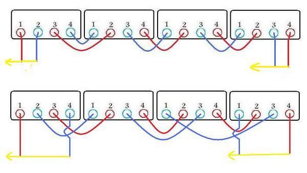
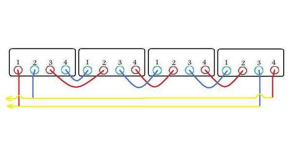
__ Below I've included that pic.diagram with it's alt.wire-leads (colored as Bruce chose), with the colors located as Bruce had connected them to his stator.
In addition, I've included an updated-version which indicates the necessary wire-swap (to prevent the HOT-circle short-circuit (that Bruce ran-into).
(Note that there was no-need to change the green-wire [as-well as the red] !)


" with Ducati's unique winding scheme of which the benefit still eludes me. "

____ To just touch-lightly on that,, If you understand how a DC.ignition-coil works, then you ought easily also understand how the two alt.stator-windings's pulses of DC induce identical-DC into EACH-OTHER ! _ Cuz the way that the two stator-windings are coiled-up so close-together, makes it impossible for them to-NOT influence each-other ! _ (Cuz if they actually didn't, then ign.coils couldn't work the way they do either !)


" I know, 'pull/pull' or whatever...:? "

____ That "pull/pull" term was what I-myself came-up with in attempt to describe the 'action' of the process,, but for those who already understand, that action should be called 'mutual-induction', (as the dual half-wave rectification process forces the two windings to take-turns playing the 'primary' & 'secondary' roles !).
__ I've been wondering if your mosfet-R/R.unit is somehow able to take advantage of that (Ducati type) co-induction effect, in order to explain your magic/extra power-output !?
But in such case, I'm SURE it's not possible with any single-phase R-R.unit with only one-pair of AC.input connected-up like 'scheme-E'.


" (though if that's the case, then why do I get higher outputs without it?) "

____ As I've tried to explain (within OTHER-threads),, full-wave rectification of alt.stators (wound as Ducati does), causes INCREASED alt.winding-impedance, instead of DECREASED impedance (as-with the DUAL half-wave rectification) !
AND-also,, if the load is rather light, then there's no significant current-flow to induce a copy of itself within the opposed-winding. _ But whenever the load is drawing high-current from one winding, THEN that same current-amount (transformed as available power), becomes mirrored in the OTHER-winding (that's otherwise dead at-the-moment due-to the HALF-wave rectification).
That means that EXTRA power only comes to be produced ONLY when the load-system demands it. _ A sort-of SELF-regulating alternator !


" ('polarity' may not be the right terminology, since it's ac, 'direction' might be more correct?). "

____ Unfortunately, (like so many other things in this world), insufficient terminology has left that word 'polarity' to be used for either DC or AC.
But I sure agree with you that the word ought to be modified for referencing 'AC' ! _ (If I were world-dictator, then a term meaning 'absolute-polarity' would be used for AC.)


" To correct it, you'd need to reverse the 'polarity' of all the windings on one set, either one would do " ...

____ Wait-a-minute-now... "either one would do" ... That's correct but, then that reasoning would be in direct-odds with your advice that BOTH the red AND the green wires need to be moved/swapped !
So WHICH are you maintaining is the actually-correct line of reasoning, Bill ??


" OR, just swap the red AND green on your setup, which achieves the 'e' scheme that you originally intended... "

____ I hope you're not going to continue to stick with THAT ! _ Cuz only ONE of those two colors needs to be swapped-out ! _ (Or-else Bruce will be right-back where he started !)
__ Look-at the COLORED diagrams (I'm going to post), and-THEN see what you think about this-ISSUE !


" I still like the '3 section' mod on the 6 coil stators. "

____ Yes, I agree ! _ As not-only does that multiple-parallel arrangement also work just as well (as the std.arrangement), with low-current loads,, it's also the-BEST for rather transferring MOST-all of the alternator's produced power out-TO the LOAD-system, (and thus leaving much-reduced power to be wasted by the alt.stator),, even-when the load-system's demand for current becomes extra-HIGH (like when high-power headlight-circuits are activated) !
__ What was particularly enlightening about that tested parallel-arrangement, is that it pretty-much PROVED that which I've always contended about alternators not actually producing any 'voltage' -(of which adds-up ONLY when arranged in 'series') ! _ As you were able-to obtain AT-LEAST as much alt.power and charging-system voltage, with the power-coils arranged in 'PARALLEL' (as when left in 'series') !
(So apparently, the only reason for leaving winding-coils in 'series', is due-to the added expense of connecting all the coils in 'parallel' [compared-to simply left in series].)
So that revelation should get those who've had mere BASIC-training to realize that 'power' is indeed 'additive' regardless of being in 'series' OR 'parallel', and that the alt.power-coils need-NOT be arranged in series (in-order to get the resulted/measured output-voltage ADDED-up), to become increased !
__ I wonder how MotoMike would've responded to that 'proof' that alternators don't really produce actual 'voltage' !?


" Bob likely has a preferred method that may be equally up to the task, "

____ Actually,, for addressing best possible low-RPM alt.power-output,, Ducati's alt.winding arrangement would have-to be replaced with standard/continuously-wound type power-coil windings.
Which considering the intricate complexity of all the required tricky rearrangement-fussing with the stock dual coil-windings, would-not make a complete rewind-job too-much more work to get accomplished.
__ (For decades, I've had a 6-pole stator that's especially-wound for my-own RT450/dual-ignition project. _ It's complexity would amaze you, [with it's FOUR separate winding-circuits] !) _ As it has one power-coil for the std.R/T-type ignition, two more straight-wound power-coils for when the high-beam is turned-on, and two other power-coils with Ducati's dual-windings (for charging the battery [with only one of the dual-windings] and powering the low-beam [with the opposite dual-winding], with the battery powering the second ign.circuit !
Hows that for complexity ?
It was all planned-out to help keep my 450-project's system WELL-balanced, for a NO-regular needed system !


Enlightening-Cheers,
-Bob

UPDATE - I've now added the colored-versions of the pic.diagram posted by Bill, with hopes that they help clarify the raised-issues.
__ I should think-not,, but if need-be, I'll also add a couple other versions showing the resulted indication of swapping BOTH the red AND the green wires, (as seems to-be a [unlikely!] popular-idea [for some crazy-reason] ).
You do not have the required permissions to view the files attached to this post.
PLEASE NOTE... If this-post is not-yet signed-off with '-Bob', then I'm still in the process of completing it,, and if not also included with 'DCT' near bottom as well, then I may edit this post's wording at a later time. - Dct.Bob

wcorey
Posts: 323
Joined: Sun Jan 31, 2010 1:50 am
Location: MA USA

Re: Troubleshooting Alternator Wiring

Postby wcorey » Mon Aug 19, 2013 2:16 pm

Bob,

Unless I misread (possible of course) Bruce's original description of what he did, I stand by the information laid out in my previous post.
And if need be, I'll resurrect the test setup and prove the results, as I had already done back then.

And/or Bruce can just SWAP the red and green wires :twisted:...

Maybe I wasn't making myself clear enough but the first diagram you refer to as being wrong really isn't.
Well, it is wrong but it's meant to be so, as it illustrates what Bruce did that doesn't work. After which I then go on to show how to correct it.
One of those corrections happens to result in the 'e' scheme that you don't particularly care for but
has been proven to be a solid performer none-the-less.

I know this because during the course of testing, I ran into the very same situation and documented it in the material that I've been pushing you to read.
That you obviously haven't...

Bruce was on exactly the right track for what he intended to accomplish and had a 50/50 shot at getting the red/green placement right, he just came out on the wrong side of the guess. No harm done...


I'm off to work so don't have time for a detailed discussion now but will surely continue this later...

DewCatTea-Bob
Posts: 2897
Joined: Sun Nov 01, 2009 10:53 am
Location: Near SE side of Lake Michigan

Re: Troubleshooting Alternator Wiring

Postby DewCatTea-Bob » Mon Aug 19, 2013 11:30 pm

[quote= wcorey ...
" Unless I misread (possible of course) Bruce's original description of what he did, I stand by the information laid out in my previous post. "

____ It seems that you HAD indeed read it correctly ! ...
ecurbruce wrote: The alternator has four wires exiting the case, black, green, white, and red. The two sets of series coils are isolated from eachother.
The white wire and the red wire have continuity, and so are connected to one set of coils.
The green wire and the black wire have continuity, and so are connected to the second set of coils.
wcorey wrote:It's likely you've got the polarity backwards between the two coil sets and they're cancelling each other out.
Try black/red, white/green,
But once Bruce first made the mistake of stating that "I think I will swap the red and green wires and re-test for system voltage,",, then ever-since, you've been STUCK still-thinking the-same is still the correct reconnection-fix.


" And if need be, I'll resurrect the test setup and prove the results, as I had already done back then. "

____ Certainly by NOW you should realize that that's not necessary, (and I'm sure YOUR setup didn't happen to have red & green wires [connected-up to the stator's normally-grounded lead-ends], anyhow) !


" And/or Bruce can just SWAP the red and green wires "

____ I can't believe that you're STILL promoting that worthless swap-fix even after I've posted more than one diagram-scheme clearly-SHOWING the error that still seems to elude you !
__ Bruce, some help please ! _ Who's actually-right about this (rather silly) issue ?
Bill, or me & 'wcorey' ?


" One of those corrections happens to result in the 'e' scheme that you don't particularly care for but
has been proven to be a solid performer none-the-less. "

____ Indeed so, but could-be even more "solid".
Bet you can't find a professionally-produced setup that's set-up & mass-manufactured like-that, (without first being balanced-matched to a rather LOW-tolerance) !


" in the material that I've been pushing you to read.
That you obviously haven't... "

____ Sorry but, the circumstances that would allow me to sift-through all-that (looking for nothing in PARTICULAR), have not-yet occurred.


" Bruce was on exactly the right track for what he intended to accomplish and had a 50/50 shot at getting the red/green placement right, he just came out on the wrong side of the guess. "

____ I don't think he guessed,, cuz in that case, he then would've naturally next tried the flip-side of the coin, (instead of wondering what could be wrong). _ Thus therefore he must've been led-astray by that posted drawing (that I hadn't conceived).


" I'm off to work so don't have time for a detailed discussion now but will surely continue this later... "

____ And here I had assumed that you must be on vacation (since it's been near a year since you last placed any extended-posting).
__ Your post-contributions are appreciated (and have been missed), Bill ! _ But you should realize that if DewCatTea-Bob maintains anything as being actually-true, then you should LOOK-elsewhere for fault, (even if it's towards yourself).


Hopeful-Cheers,
-Bob
PLEASE NOTE... If this-post is not-yet signed-off with '-Bob', then I'm still in the process of completing it,, and if not also included with 'DCT' near bottom as well, then I may edit this post's wording at a later time. - Dct.Bob

ecurbruce
Posts: 299
Joined: Fri Apr 01, 2011 12:43 am
Location: Lakeland fl

Re: Troubleshooting Alternator Wiring

Postby ecurbruce » Tue Aug 20, 2013 12:49 am

Hey Bob & Bill!

How crazy is this?
" And/or Bruce can just SWAP the red and green wires "
____ I can't believe that you're STILL promoting that worthless swap-fix even after I've posted more than one diagram-scheme clearly-SHOWING the error that still seems to elude you !
__ Bruce, some help please ! _ Who's actually-right about this (rather silly) issue ?


OK, let's put it this way, my verbiage and terminology is always minimal or marginal at best, but as I go back and re-read all of the posts in this recent thread, I can see the opportunities for confusion. Yes, I said red and green wires, maybe I should have expressed that as the red and green terminal... And the swap would be for one of the wires on the black and white terminal. So that would have been swapping one of the wires off the red and green terminal for one of the wires from the black and white terminal.
Bill understood that by reading between the lines, and knowing where I was headed.
Bob, taking every detail with a literal meaning can see the incorrectness in my terminology and your goal is to correctly portray the details so our readers can correctly understand the details of what we mean to accomplish here...

I can see the correctness in both points of view, and if it points me in the right direction to solve my problem, then it's all good!

So today, on the AC terminal to the left ( in our reference photo of my regulator) I attached the green wire and the white wire together. On the other AC terminal I attached the red wire. I have regulated DC voltage charging the battery, and running the headlamp. Next with the green and white still connected to the left terminal, I connected only the black wire to the right AC terminal, and have regulated DC charging battery and running headlamp. Next with the green and white wires on the left AC terminal, I attached the black and red wires to the right AC terminal, and I have regulated DC voltage charging the battery and running the headlamp, as it should be now. That's a swap of one wire from each terminal, to configure it to a true "E" connection.

More testing to come next, my RPM meter malfunctioned, and needs replacing, but I was getting charging level voltage at somewhere around one third throttle. And a bright 60 watt halogen headlamp. My ignition coil is .3 ohms resistance, did you-guys see the Nippon denso retro-fit ignition system I am using?

Bruce.

DewCatTea-Bob
Posts: 2897
Joined: Sun Nov 01, 2009 10:53 am
Location: Near SE side of Lake Michigan

Re: Troubleshooting Alternator Wiring

Postby DewCatTea-Bob » Tue Aug 20, 2013 1:11 am

[quote= ecurbruce ...
" How crazy is this? "

____ I agree that this silly issue should-not have gotten drawn-out to such a degree as it has, (Bill often doesn't tune into my-wavelength).


" Yes, I said red and green wires, maybe I should have expressed that as the red and green terminal... And the swap would be for one of the wires on the black and white terminal. So that would have been swapping one of the wires off the red and green terminal for one of the wires from the black and white terminal.
Bill understood that by reading between the lines, "

____ Well if he did,, then by our 2nd.round, he should've at-least mentioned either the black or white wires (instead of continuing-on with just red & green) !


" Bob, taking every detail with a literal meaning can see the incorrectness in my terminology and your goal is to correctly portray the details so our readers can correctly understand the details of what we mean to accomplish here... "

____ Indeed-so, Bruce. _ Otherwise most everyone would be doing even-WORSE than merely wasting their time !


" I can see the correctness in both points of view, "

____ Well that makes ONE of us, cuz I sure can't see how touching BOTH green AND red terminal-connections could properly-alter the circuit-arrangement !


" on the AC terminal to the left ( of my regulator) I attached the green wire and the white wire together. On the other AC terminal I attached the red wire. I have regulated DC voltage charging the battery, "

____ That means that you're only achieving DC.charging-juice from the power-output of just your white/red alt.power-winding ! _ And then getting 60 to 80% of what power is totally possible (depending-on load & RPM}.


" with the green and white still connected to the left terminal, I connected only the black wire to the right AC terminal, "

____ And likewise, that means that you're then only utilizing alt.power from just your black/green alt.power-winding ! _ And then also only obtaining ABOUT the same amount of power (as gotten alone from the other-winding).


" Next with the green and white wires on the left AC terminal, I attached the black and red wires to the right AC terminal, and I have regulated DC voltage charging the battery "

____ Now THAT-way, you're then using the same bridge-rectifier to process BOTH alt.winding together at-once, and thus making usable the power from both alt.windings (available together). _ But unlike with a REGULAR alt.stator-winding,, the available power from both power-windings together, is-not doubled that of just either power-winding alone, (as would normally be the expected case with a std.stator -[built by other than Ducati] ). ...
At low-RPM and with nothing other than the battery to consume power, the total power-production of both power-windings together is then indeed pretty-much doubled that of when only one alt.winding is connected, just as ought-to be expected !
However at higher-RPM and with high-current loads pulling juice through both alt.windings, the amount of TOTAL-power from both could possibly drop to little-more than either alt.winding on it's own.
__ One-thing that's really-good though, is that when the load-system happens to have very-low resistance, this parallel-arrangement is then much-more efficient than the commonly-done (rather simple) series-arrangement !
__ So Bruce now has TWO*advantages over other n-c 6-pole (common type)- full-wave charging-systems ! _ (* The other being his addition of an extra pair of power-coils.)
Although his chosen parallel-arrangement doesn't offer any real power-advantage (over the common series-arrangement), until a HIGH-power headlight is connected.


" to configure it to a true "E" connection. "

____ For the enlightenment of others, the so-called 'E-scheme' is-not some well-established/officially-named technical-scheme,, but rather merely, just a proposed scheme which just-happened to be 5th (letter 'e') to be submitted.


" More testing to come next, but I was getting charging level voltage
And a bright 60 watt halogen headlamp. "

____ You ought-to try starting-out with a near-dead battery, and see if your normal-riding will charge-up the battery (at all) with lights on,, with just one, and-then both alt.power-windings connected-up.


Hopeful-Cheers,
-Bob
PLEASE NOTE... If this-post is not-yet signed-off with '-Bob', then I'm still in the process of completing it,, and if not also included with 'DCT' near bottom as well, then I may edit this post's wording at a later time. - Dct.Bob

wcorey
Posts: 323
Joined: Sun Jan 31, 2010 1:50 am
Location: MA USA

Re: Troubleshooting Alternator Wiring

Postby wcorey » Tue Aug 20, 2013 1:17 am

The Defense rests.
What say you, Bob?

DewCatTea-Bob
Posts: 2897
Joined: Sun Nov 01, 2009 10:53 am
Location: Near SE side of Lake Michigan

issue settled ?

Postby DewCatTea-Bob » Tue Aug 20, 2013 1:32 am

wcorey wrote:The Defense rests.
What say you, Bob?

____ Well, if I was the one who was wrong, then I'd be admitting it !

___ We can drop the matter now, and move-on to whatever (is hopefully more productive).

____ Bruce, what do you use for a light-switch,
or do you ALWAYS run with lights left-on ?


Duke-Cheers,
-Bob
PLEASE NOTE... If this-post is not-yet signed-off with '-Bob', then I'm still in the process of completing it,, and if not also included with 'DCT' near bottom as well, then I may edit this post's wording at a later time. - Dct.Bob

wcorey
Posts: 323
Joined: Sun Jan 31, 2010 1:50 am
Location: MA USA

Re: Troubleshooting Alternator Wiring

Postby wcorey » Tue Aug 20, 2013 1:50 am

Bill understood that by reading between the lines, and knowing where I was headed.
Bob, taking every detail with a literal meaning can see the incorrectness in my terminology and your goal is to correctly portray the details so our readers can correctly understand the details of what we mean to accomplish here...


Very eloquently put Bruce... You're obviously both a Scholar and a Statesman, on your good days anyway :D.

Now, speaking of understanding... I think Bob and I have our red and/or green wires crossed.


Return to “Ducati Singles Main Discussions (& How to Join)”

Who is online

Users browsing this forum: Boxprod and 24 guests