By: jbcollier...
" The reason I use a 35w headlight as then I get the battery charging under 3000 rpm. Going to a 55w bulb means its not charging the battery until 5000 rpm. The 35w headlight and 35ishw ignition system
chew up most of it up. "
____ Thanks for getting back to my question concerning why you run only a 35w head-light, after going to all the trouble of such extensive alternator-modification ! ...
I now understand (for certain) that in YOUR case, it was not more powerful lighting that you need to run, (as is most often the case with others), but rather, your particular increased-power need is for your much extra hungry ign.system set-up to be kept fed.
I had heard that a Rita type ign.system consumed considerable extra power-juice, but I didn't think it would be so much as 35-watts worth !
Did your 3-ohm ign.coil come with that ign.system ? _ And the 1-ohm ballast-resistor as well ?
Those two units properly connected in series, means they could draw 3-amps with a 12-volt power-source, (providing the Rita-box allows that), until the ballast heats-up & does it's job cutting current-flow through the ign.coil.
So I'd expect the ign.system to consume that 35-watts only until it heats-up, and after running a fairly-short time, then cut-down on current-draw.
I assume that you've confirmed the 35-watts of power-consumption when cold but, have you not checked the ign.system's current-draw after the ballast-resistor has fully warmed-up ?
It would also be of interest to know how much amp.juice the Riti-box alone draws ! _ As the ign.coil-circuit ought merely draw it's max.consumption for a short period during the relatively brief times when a spark is to be produced. _ Thus the expected max.amp-draw should average-out to very much less than the expected 3-amps.
But of course I don't really know for sure what the Rita-system is actually doing, however I'm expecting that it may not really actually consume so much wattage at ALL times, and therefore may leave you more excess power-juice than otherwise expected. (?)
__ One thing I know I would do if it were my set-up, is install an ammeter at least long enough to get to know what I'm having to actually deal with !
And if I learned that the ign.system actually required all that power all the time, I'd then be sure to never install such a hungry ign.system on a Duke that's intended for any extended city-street riding !
Hopeful-Cheers,
-Bob
six coil alternator in a narrow case 250
Moderator: ajleone
-
DewCatTea-Bob
- Posts: 2897
- Joined: Sun Nov 01, 2009 10:53 am
- Location: Near SE side of Lake Michigan
Re: six coil alternator in a narrow case 250
PLEASE NOTE... If this-post is not-yet signed-off with '-Bob', then I'm still in the process of completing it,, and if not also included with 'DCT' near bottom as well, then I may edit this post's wording at a later time. - Dct.Bob
-
MotoMike
- Posts: 487
- Joined: Wed Aug 04, 2010 3:40 am
Re: six coil alternator in a narrow case 250
** first paragraph removed,.
All that said, the main reason I'd switch to a 12 volt system is if the original 6 volt rectfier/regulator went south. replacing it is pricey and sketcy.
I would probably then switch to an Ebay regulator something like this one
http://www.shindengen.com/resources/con ... 20Data.pdf
I picked this one just because it has a data sheet which will allow discussion. also 3 phase are more numerous. this one shows that the control cirucit switches the scr;s in and out as needed to provide output. It is rated at 35 amps, so would have plenty of capacity even when you consider that you would have to de-rate it a bit. I say de-rate becaus in a 3 phase system, the duty cycle of the diodes/scr's employed would be 1/3 of the time, in a single phase system, you would connect your alternator output to just two input wires instead of three and the 4 diodes/scr's then employed would each be used 1/2 of the time. So you're fusing your upper limit at 11 amps should allow this regulator to we working pretty light duty. there are lots of ebay regulator/rectifiers out there, but usually they don't give you the specs. If you find one for a specific motorcycle you could track down it's prints to see which wires go where. Just because they have additional wires for lights and tac etc, doesn't mean it wouldn't work. Probably even the small modern scooters would have enough capacity for our dukes.
I see a good number of single phase regulator rectifiers there, but the most of new ones are for chinese scooters and no specs are published.
Last edited by MotoMike on Sat Apr 30, 2011 10:52 pm, edited 2 times in total.
-
DewCatTea-Bob
- Posts: 2897
- Joined: Sun Nov 01, 2009 10:53 am
- Location: Near SE side of Lake Michigan
Re: six coil alternator in a narrow case 250
MotoMike wrote:I'm just thinking outloud here, so bear with me. the original wattage rating of the alternator was based on current that the coils could handle, but you were using only half of them at a time which would be somewhere around 11 amps. when you put the coils in series and effectively double the voltage output but keep the same current through them you would ( P or watts=ExI )double the wattage the alternator could supply. So if you switch it over to 12 volts, still fuse it at some where around 11 amps, wouldn't you have excess wattage capacity at your disposal? A 6 volt 35 watt bulb is drawing more current than a 12volt 55 watt bulb. P/E=I 35/6=5.8 amps while 55/12=4.58 amps, so 35 and 55, plus 5 or so for the tail and a couple for those status lights in the headlight shell would put you around 100 watts but still under the rated 140 (conservative) 160 if the original was an 80 watt alternator.
____ Mike, I really want to comment on all this but, it would be more fair to give you another try thinking it all through again & editing it first.
I'll add some thoughts of my own, to possibly help inspire some more thoughts for you to consider-in.
__ I have doubts that the alt.wattage-rating was much at all based on the amount of current that the coil-windings could properly handle.
The stock 6-pole 4-core/coil alternator was rated at 60-watts, (but that figure is much suspect, as it was not stated as being produced at any particular RPM).
If that rating is trusted, then that could be either 10-amps @ 6-volts or 5-amps @ 12-volts.
Another involved mystery is that the stock charging-system only uses half of what's available from it's alternator, so then we might be led to think that it only supplies 30-watts of charging-power,, but we know that can't be the case because the stock load-system can consume more than that amount and yet the battery always remains well charged !
__ You seemed to have overlooked a basic error...
If each of the two alt.windings were to be producing 6-volts & 5-amps (6v x 5a = 30w x 2 = 60w total,, AT some particular RPM), then putting the two in series would provide 12-volts but still just 5-amps, and that does NOT "double the wattage" , (12v x 5a = 60w) !
In order to double the wattage as well (as the voltage), you'd still have to have a SECOND/SEPARATE pair of alt.windings, (of which you've effectively given-up one of). _ So it seems you've simply forgotten that you no longer have two PARALLEL alt.windings to work with, (which WOULD've doubled the wattage as well, if your ghost series alt.winding remained in the picture).
____ With all this added thought kept in mind, how about simply editing your post to reflect all that which you should have had completely straight, and restate your remaining points,, cuz you should still have some worth-while notions remaining for good/further discussion.
Hopeful-Cheers,
-Bob
PLEASE NOTE... If this-post is not-yet signed-off with '-Bob', then I'm still in the process of completing it,, and if not also included with 'DCT' near bottom as well, then I may edit this post's wording at a later time. - Dct.Bob
-
MotoMike
- Posts: 487
- Joined: Wed Aug 04, 2010 3:40 am
Re: six coil alternator in a narrow case 250
my first sentence states that you are using only half the coils at a time. I thought that is what you have previously conveyed. Since I can't find a schematic on how the rectifier regulator is wired (and I know you won't show me one)It is certainly possible I don't know how this rectifier regulator is wired and might be operation under a misconception. All my discussion from that point on is based on that assumption. If that assumption were correct, then I think the subsequent annalysis would be right. If it is wrong, please explain how they are being used.
I have removed the discussion, though it still appears in your post.
I have removed the discussion, though it still appears in your post.
-
jbcollier
- Posts: 86
- Joined: Sun Oct 10, 2010 2:30 am
Re: six coil alternator in a narrow case 250
Yes, the Rita is a bit of a power hog and it doesn't like voltages below 10.5v or so. Low voltage triggers a random firing pattern that sounds a good deal like a cratered engine! I have never hooked up an ammeter even though I have several Fluke meters -- it all worked so well, I did check the voltage output of course, why bother. However, in the interest of furthering the scientific progress of the human race, I'll do just that when I get the bike down from it's winter storage -- my back's out so I haven't been in a rush on that account.
When I purchased the Rita system, I was told that a primary resistance as high as high as five ohms would be fine with a single as current draw is a real problem with the Ritas on a stock single's charging system. I compromised on a green twin output Dyna with a one ohm ballast resistor as my engine is twin plugged.
When I purchased the Rita system, I was told that a primary resistance as high as high as five ohms would be fine with a single as current draw is a real problem with the Ritas on a stock single's charging system. I compromised on a green twin output Dyna with a one ohm ballast resistor as my engine is twin plugged.
-
DewCatTea-Bob
- Posts: 2897
- Joined: Sun Nov 01, 2009 10:53 am
- Location: Near SE side of Lake Michigan
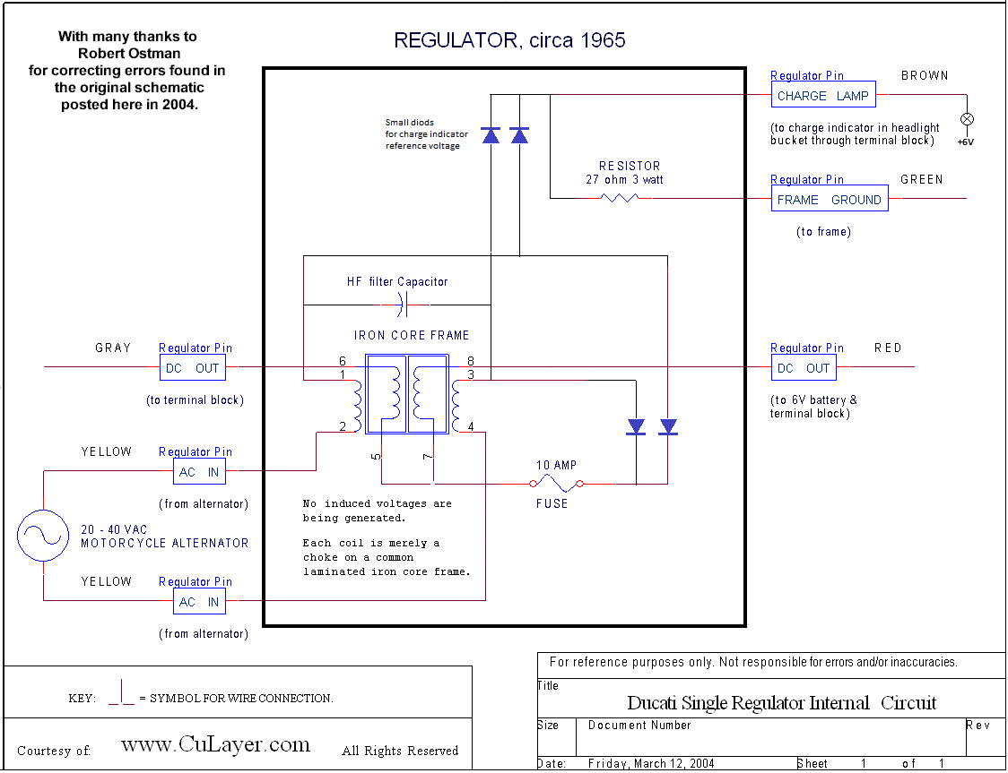
Stock N-c R.R.Black-box Internal-circuit Set-up
By: MotoMike...
" my first sentence states that you are using only half the coils at a time. "
____ Right, and I believe I had taken that into account as intended. _ Meaning that at the moment when one of the two alt.winding's positive-pulse is allowed into the system, the other alt.winding's negative-pulse is entirely ignored, thus dead as far as the system is concerned,, and vice-versa, when the other alt.winding switches-over to its positive cycle.
" I thought that is what you have previously conveyed. "
____ I'm sure that I must've also mentioned at the same time that the reason for that circustance, is due to each alt.winding only being merely half-wave rectified.
" Since I can't find a schematic on how the rectifier regulator is wired (and I know you won't show me one)It is certainly possible I don't know how this rectifier regulator is wired and might be operation under a misconception. "
____ I'm not sure if you're referring to the stock black-box which is meant to work with the stock alt.stator (which grounds the internal lead-ends of both alt.windings),
or some other rect.reg-unit. _ But if you're meaning the stock-unit (for the n-c, not w-c), then I believe that Jim or someone has posted a schematic-diagram of all it's internals,
and here's a link to it for you... http://motoscrubs.com/Ducati_Electrics/Regulator.gif
__ I'm really torn between giving you a guided-tour through it all, or letting you have the fun of exploring it for the first-time, all on your own. _ I'd certainly choose to first leave you alone with it to ponder on your own for a while, IF I knew it to be 100% correct. _ However since I believe it to contain a basic error, it would be wrong of me to not warn you, so as to save you from wasting too much of your time trying to make proper sense of it all.
So as a compromise, I'll partially tip you off (for now), that the diode-arrangement scheme-drawn as a common bridge set-up, is not actual with respect to what's really found internally within the stock black-box !
__ Be prepared with a clear mind, as the internal circuit-workings are not easily deciphered without yar thinking-cap dialed to a high-setting !
After you've gotten your fill of exploration through it, let me know so we can begin discussion of this wonderfully complex piece of art-work.
Of main interest is the auto-varied choke, followed by the charge-indicator warning-light circuit.
" All my discussion from that point on is based on that assumption. If that assumption were correct, then I think the subsequent annalysis would be right. If it is wrong, please explain how they are being used. "
____ I'm not sure what all is actually encompassed within your "assumption", and also, I'm lost as to how whether my claim (that one alt.winding really is ignored while the other is being used), being actual fact or not, could possibly make a right or wrong difference, in regards to your analysis, as it was worded.
I'm thinking perhaps your end-conclusion is based on proper reasoning, but that your chosen wording just didn't cover it all fully/clearly.
Hopeful-Cheers,
-Bob
PLEASE NOTE... If this-post is not-yet signed-off with '-Bob', then I'm still in the process of completing it,, and if not also included with 'DCT' near bottom as well, then I may edit this post's wording at a later time. - Dct.Bob
-
MotoMike
- Posts: 487
- Joined: Wed Aug 04, 2010 3:40 am
Re: six coil alternator in a narrow case 250
BobI thought we were talking wide case stator, and stated two yellows and a red from the alternator, If I missed some id details, I meant wide case Regulator Rectifier.
If one half of coils is producing only half of the time, then it would have to produce the rated output for that half of the time, the load requires it instantly and can't wait for the two halves to be added together. That is the assumption I was basing my discussion on. After rectification and usually a bit of filtering, the ouput will be smoothed, so that it approximates a ripply DC line somewhere near the desired level. the load , head lights and ignition, most significantly draw current for the full 360 degrees of the alternator output. If you adjust your numbers closer to mine, then we are not that far apart. Power is addative in the loads at an instant of time. And is a function of how much voltage is across them and how much current is passing trough them bacause of thier resistance (or impedance) they have. So if the loads are consuming 60 watt for 1/2 cycle, that half of the alternator must be supplying it until we go to the next half cycle and the other half provides it. The alternator as a system then produces that output all the time.
I suggest that if I am making a mistake it is due to ignorance of the circuit's construction, not forgetting a "basic" error. Remote as the possiblility may be, It occurs to me that you might have it wrong too. I only "know" we are using half of the potential because of your comments. if as you suggest, half the coils are "dead" half of the time, one reason might be to slacken their duty cycle to make them last. If that is the case, when connecting them in series and omiting the center connection and going to full wave rectification, we might do well to de-rate them below double the stock rating.
To suggest that the system can supply only 30 watts seems on it's face to be wrong. not even the headlight would be addequitly supplied.
The Schematic supplied is interesting. thanks for that. It is an old fashioned design but uses a full wave rectifier, and instead of limiting current through the bridge by employing a switching SCR or the like, limits it by saturation in the coils shown. they typically would use a highly permiable common iron core for all the coils. I think I see how it works, but if it is inaccurate or not the one that applies to our discussion, I'll not get too far into it. at least not now.
I know you are not thin skinned bob. I must at times chuckle over my frustration with you as when it comes to clear wording, I opine you are the kettle calling the pot black.
Kind regards,
Mike
-
MotoMike
- Posts: 487
- Joined: Wed Aug 04, 2010 3:40 am
-
ecurbruce
- Posts: 317
- Joined: Fri Apr 01, 2011 12:43 am
- Location: Hurricane mills TN
Re: six coil alternator in a narrow case 250
bob wrote, "Please explain what's wired up thus far and what's not..."
So far I've wired the alternator two separate isolated series circuits of six coils each, with a four wire cable exiting the engine cases. I used a 16 gague four wire cable replacement lamp cable from Lowes home improvement. This gets me wired and out of the engine where I have four wires that can be wired in any one of the optional wiring diagrams. My system will use a 12 volt battery and a single phase regulator /rectifier with the two alternator leads and one battery lead that I mentioned earlier in this thread.
This is as far as I can proceed at this time, because my crankshaft is at Syd's for rebuild, and until I reassemble engine, I cannot test any wiring since I can't spin alternator.
-
DewCatTea-Bob
- Posts: 2897
- Joined: Sun Nov 01, 2009 10:53 am
- Location: Near SE side of Lake Michigan
Re: six coil alternator in a narrow case 250
By: MotoMike...
" I thought we were talking wide case stator, and stated two yellows and a red from the alternator, "
____ Mike, as this thread has progressed, I-myself noted nothing that diverted towards any discussion pertaining to any of the wide-case type charging methods, (especially, anything having to do with the w-c regulator),
with the exception of Bruce once mentioning that his modified n-c alt.stator could possibly be used in the same manor as a w-c alt.stator, once he would ADD a center-tap "red" wire-lead. _ So I think that is what led you off the established track which I've remained on,
and I didn't notice any given clue that you-yourself had switched-over solely to any of the w-c methods.
" If I missed some id details, I meant wide case Regulator Rectifier. "
____ The w-c charging-system methods are considerably altered from those of the n-c equivalents, and trying to learn both at once could lead to certain confusion. _ However the main detail which remains same for both methods, is the fact that only 'HALF-wave rectification' is performed on their respective pairs of alt.winding-circuits !
Unfortunately, I know of no schematic-diagram of the w-c type R.R.box.
It's main-confusing difference is that instead of passing both sets of POSITIVE-pulses to the battery's POSitive-terminal/post, it instead passes both sets of NEGATIVE-pulses directly into Ground !
__ The stock w-c alternator was rated at only 70-watts, so it's a fair mystery as to why it's six core-coils don't equate 90-watts, since the n-c stator's four core-coils are claimed to produce 60-watts...
I've never unwound either type of stator, so I can't say whether the w-c stator has fewer total turns of coil-loops, so as to explain the wattage difference per core-coil.
Next, by MotoMike...
" If one half of coils is producing only half of the time, then it would have to produce the rated output for that half of the time, "
____ I understand why you think that Mike... I'm gathering that you're stating that if the alternator is at an RPM when it's producing it's full rating of 60-watts, that then either alt.winding must supply that 60-watts, ONE at a time. _ But that's without regard as to whether we're in reference to '0-to-peak', or, 'peak-to-peak'.
When the full-cycle is rectified to half a cycle, then the remaining half-cycle is only half the power, (with the other half ignored),, but then we still also have the OTHER full-cycle which only half of is not ignored... And so the two separate half-cycles combined (within the very-same full time-period as a single FULL-cycle), charge the battery at the same rate as ONE alt.winding would do alone.
We have to keep in mind that the Duke-alternator is as if 'two-in-one' and it's combined-effort is what it's rating is based upon, and also on top of that, that it's never been clear exactly how Ducati went-about rating their alternator's wattage-output !
" the load requires it instantly and can't wait for the two halves to be added together. That is the assumption I was basing my discussion on. "
____ Well maybe you're still thinking in 'AC', (or perhaps unfiltered 'PDC'), as the two DC-halves don't really need to occur at the very-same point in time, in order for their combined values to result within the storage-battery.
Also we need to keep thinking mainly in 'wattage', not just voltage or amperage, whenever in regards to charging-systems with storage-batteries.
" After rectification and usually a bit of filtering, the ouput will be smoothed, so that it approximates a ripply DC line somewhere near the desired level. "
____ That seems as an example not particularly compliant with Duke charging-systems, as the charging-system "output" remains FULLY Pulsating-DC, and once blended with a (not too small) storage-battery, then becomes near ripple-less & nearer to the battery's (adjusted) voltage-level.
" the load , head lights and ignition, most significantly draw current for the full 360 degrees of the alternator output. "
____ Most definitely true! ... So the battery has to fill-in the missing juice-levels (within each 360-degree cycle), or else the loads will rapidly go On & Off (if they can keep-up with the pace) ! _ However, the missing-levels are not 180-degrees long (as might be thought), cuz when one of the two half-cycles is dead, then the OTHER is live !
" If you adjust your numbers closer to mine, then we are not that far apart. "
____ I'm sure our result differences must be due to us not both being in reference to the very-same originally given specs.
" Power is addative in the loads at an instant of time. "
____ I'm not real sure what you're meaning to convey in that sentence...
And are you meaning before or after rectification & RMS adjustments ?
" So if the loads are consuming 60 watt for 1/2 cycle, that half of the alternator must be supplying it until we go to the next half cycle and the other half provides it. "
____ Well that notion would seem so, without looking at the whole-picture...
__ First I ought point-out that if the total-load were to be 60-watts, the stock (so-called) '60-watt' alternator (along with it's stock charging set-up), would not keep it's battery charged ! _ And once the battery fell short of keeping the ignition firing, then the whole system would come to a stop.
__ Now to explain your notion in another viewpoint...
If either of the two alt.windings happened to be in the position of being able to supply 'The 60-watts', then that amount of power is to be expected between the peaks of BOTH the positive AND the negative halves of the FULL cycle !
But since the stock-system ignores the negative-half, then only 30-watts of power remains ! _ But yet the stock charging-system still ends-up with 'The 60-watts', due to the (extra) positive half-cycle from the OTHER/second alt.winding (which happens to be within the SAME time-period as a 'full-cycle', [however 180-degrees out of sync]) !
So the combined end-result, is an output that's virtually the same as a full-wave rectified output from just ONE of the alt.windings ! _ (As if the alternator were to be merely just a straight-forward single-alt.winding, type.)
__ Why Ducati did it the way they did, is open for varying speculation, but, whoever thought to do it that way, (instead of just one single/larger alt.winding), is my-kind-of-people,, as I also don't believe in putting all my eggs in one basket.
" The alternator as a system then produces that output all the time. "
____ Well by now you must understand that it's actually only HALF that 60-watt amount, half the time, (in the stock system). _ BUT, keep in mind that that "time" happens TWICE as often ! _ (Certainly you're aware [just for instance]- that when a 60-hertz full-wave cycle is full-wave rectified, it then becomes 120-hertz !)
Now I expect the cogs to really be meshing in your head, if you haven't already grasped that which I've been meaning to convey thus far.
__ For confirmation of what's concluded here,, the stock system has TWO 30-watt positive DC-pulses occurring within the SAME length of time as a full-cycle (of the 60-watts of AC),, thus the stock-system still produces the expected 60-watts total, even though HALF of the 60-watt AC-cycle is ignored. - (That's to say the negative halves of both provided AC-cycles).
" I suggest that if I am making a mistake it is due to ignorance of the circuit's construction, not forgetting a "basic" error. "
____ For this discussion, all you've really needed to know is that the alternator's two AC-outputs are both only half-wave rectified, and you've seemingly understood that circumstance quite well enough,, therefore we're likely back to you having made an oversight type of basic-error, (concerning how much power the alternator ought actually produce along with whatever it's particular/chosen arrangement).
" Remote as the possiblility may be, It occurs to me that you might have it wrong too. "
____ Like-mindedly, if I were myself without my experience with Ducati-electricals, and I then read DewCatTea-Bob's posts with such incredible claims, I TOO would then have my doubts that DCT-Bob really has everything all perfectly straight !
But I assure you that I'm not the type who posts much stuff without being quite reasonably sure that it's certainly correct.
" I only "know" we are using half of the potential because of your comments. "
____ Well if you double-check by thinking it out for yourself,, how could it be possible to do any rectification other than 'HALF-wave', if one end of each alt.winding is grounded ??
Or in the case of the w-c set-up,
how could other than 'half-wave' rectification be accomplished, if the alt.center-tap connects to the positive-terminal/post of the battery ?
__ And you certainly know that an AC-circuit must connect to a full-wave bridge set-up, before any other part of the resulting DC-circuit, (in order to successfully obtain full-wave DC), right?
" if as you suggest, half the coils are "dead" half of the time, one reason might be to slacken their duty cycle to make them last. "
____ Well I really haven't meant to indicate that the alt.windings are "dead" half the time, but rather that their negative-pulses are all completely ignored,, thus both alt.windings are not providing power-juice/current, half the time.
__ And as I've suggested in past thread-posts, it might be that it was done the way it was, so as to help prevent over-heating of the coil-windings.
" If that is the case, when connecting them in series and omiting the center connection and going to full wave rectification, we might do well to de-rate them below double the stock rating. "
____ Considering that increased heat reduces current-flow, I agree that your notion (concerning the ACTUAL power-rating, with both alt.winding-circuits in series), may ought be the case.
__ But we'd have to have some reasonable measurement test-results, in order to then declare a reasonable percentage of de-rating.
" To suggest that the system can supply only 30 watts seems on it's face to be wrong. "
____ I-myself never actually suggested that ! _ Only meant to make the point that the factory-rating of 60-watts must therefore have been determined AFTER the half-wave rectification process, cuz if the factory alt.rating was attained before the stock (half-wave!) rectification became implemented, THEN the remaining available 30-watts of power-capacity would be OBVIOUSLY insufficient !
(That's more than a fairly-important revelation, is it not !?)
" not even the headlight would be addequitly supplied. "
____ Indeed, of course ! _ As that's part of my point which I had meant to convey, previously !
____ So as to help keep this single post from getting too deep into too many different niches, I'm splitting-off the rest of my response (to Mike's single extended-post), into my next-post (now found on the next page).
Continued-Cheers,
DCT-Bob
PLEASE NOTE... If this-post is not-yet signed-off with '-Bob', then I'm still in the process of completing it,, and if not also included with 'DCT' near bottom as well, then I may edit this post's wording at a later time. - Dct.Bob
Return to “Ducati Singles Main Discussions (& How to Join)”
Who is online
Users browsing this forum: No registered users and 34 guests