" there is not much advantage to the center tap wiring version with two wire sizes. "
____ The center-tap wire-lead set-up is merely a cheap/economical way to avoid using two separate wire-leads instead, (at the expense of circuit purity).
__ That should be adequate for your current modified alt.stator, but not the best idea for your newer consideration of the dual winding-gauge type pair of alt.windings.
" I wonder though, with one set of coils of large wire, one set of coils of small wire, isolated from eachother, exit the alternator separtely, each of the four wires run through a diode, then each circuit conected to a regulator/rectifier in parallel and out of phase. "
____ Other than your next new alt.cable containing two pairs of wire-leads, (one pair for each alt.winding-circuit), I don't really follow your circuit-plan reasoning (as worded).
" The small wire circuit would charge at low rpm, "
____ According to theory, the thinner-gauge alt.winding (with it's increased number of coil-loops), should produce a somewhat higher voltage sooner into the rev-range, (relative to a larger gauge with fewer coil-loops).
" the large wire circuit would then kick in at higher rpm. "
____ I think I know what you mean to convey by your chosen wording...
In other words, at higher RPM when the thinner-gauge alt.winding is producing plenty of volt-amps -(wattage due to more voltage than amperage), but may not be up to supplying the required amount of amperage-current (without a heat issue),, the thicker-gauge alt.winding could then be taken advantage of by relieving the other (less robust) alt.winding, by supplying superior amp-volts -(wattage that's due to a greater ratio of amperage to voltage), into the system. ...
IOW, since at high-revs when the thicker-gauge alt.winding is more freely supplying high-current (along with plenty of voltage to drive it), the current-load burden is then relaxed-off from the other/ less robust alt.winding.
Thus we have the best-of-both-worlds, as one alt.winding-circuit will provide a higher voltage at a lower rev-range, while the other's ability to more easily provide high-current, will spare the weaker one from needing to supply as much power (to keep the load-system satisfied).
" Is this sound reasoning, or am I way off base? "
____ Well, it seems to be good reasoning but, it's possible for it to be fairly well off-base, all depending on the system-type intended to go along-with...
__ Your reasoning, (if not your exact wording), seems pretty-much the same as my own (stated previously), and is thus of course not "off base", IF intended for a system which does not include a storage-battery ! ...
It must be kept in mind that systems which include a storage-battery, operate considerably more complexly than the more simple & straight-forward battery-less type systems, (which everyone tends to think in terms of the operation of *).
__ * It most always seems like most who think that their Duke's charging-system needs to be redone to produce over double the power it does as stock, wish to carry-onward as if expecting their alternator to be the sole source of power-juice and as if their new-system will have no battery to compensate during lower-RPM running. _ And also seem to overlook all the lesser known effects which a regular storage-battery has on otherwise common straight-forward logical-reasoning.
For one instance, if the ratio of battery-capacity to alternator-output is large enough, then a voltage-regulator is not needed (cuz the battery is then more capable of absorbing all the excess power that would otherwise raise system-voltage).
__ In this case, a storage-battery (that's not too small) will pretty-much make the case for larger-gauge alt.windings, irrelevant ! ...
That's because of the effect which a storage-battery has on volt-amps & amp-volts that it's connected in parallel with ! ... Whether the battery's storage is blended with high-voltage & low-current, or, high-current & low-voltage,, once blended with the battery's own pool of juice, the alt.supplied power-juice then becomes the very same as that of the battery's !
Therefore, everyone ought to look at the battery as the PRIMARY-source of power-juice, and NOT the alternator ! _ As so many seem to do.
__ So with that point realized, it should then be understood that a battery-powered electrical-system will not care whether the alternator's power-juice (think electrons), is high-current & low-voltage (as supplied by the two alt.windings in 'parallel'), or, low-current & high-voltage (as supplied by the two alt.windings in 'series') ! _ As the system's electron-total still remains the same in either case,, leaving the battery as the grand-wizard which actually determines the way all alt.power-juice is reconditioned into,
to THEN be subjected with the load-system !
__ Now I have noted that there's a fairly small advantage to using the two alt.windings in a series connection... As there is a small RPM-range where the series-connection set-up will provide just sufficient enough voltage to begin charging the battery at a lower RPM, at which the parallel set-up will not. _ But this narrow range of low-RPM (before the RPM-point when the parallel set-up begins charging), is not significant enough to be concerned with for normal riding. _ And unless the battery happens to be in dire need of charge, this small advantage is entirely insignificant.
That's because while at revs lower than necessary to begin charging, the charging-system is still donating power-juice to the load-system, thus preventing any significant discharge from the battery (which merely has to make-up the difference). _ So while the battery is then not receiving any charging-juice, then also, no alt.supplied power-juice is getting wasted by the battery, (as batteries do not store all juice which enters them!).
__ So now it should be understood that keeping the two alt.windings in parallel, is not even close to being a significant disadvantage compared to a series-type set-up !
Ya have to learn to think in terms of wattage in & wattage out, and not so much in relatively unimportant voltage-values.
Dukaddy-DUKEs,
-Bob
six coil alternator in a narrow case 250
Moderator: ajleone
-
DewCatTea-Bob
- Posts: 2897
- Joined: Sun Nov 01, 2009 10:53 am
- Location: Near SE side of Lake Michigan
Re: six coil alternator in a narrow case 250
PLEASE NOTE... If this-post is not-yet signed-off with '-Bob', then I'm still in the process of completing it,, and if not also included with 'DCT' near bottom as well, then I may edit this post's wording at a later time. - Dct.Bob
-
MotoMike
- Posts: 487
- Joined: Wed Aug 04, 2010 3:40 am
Re: six coil alternator in a narrow case 250
I guess I'd need a schematic to follow your description. Don't yet see the advantage of it, but might with further study.
Mike
Mike
-
DewCatTea-Bob
- Posts: 2897
- Joined: Sun Nov 01, 2009 10:53 am
- Location: Near SE side of Lake Michigan
Re: six coil alternator in a narrow case 250
" I guess I'd need a schematic to follow your description. Don't yet see the advantage of it, "
____ Mike, of course I'm glad to have you following along on this thread ! _ And I gather that your last post-comment (quoted above here) is actually in reference to things not stated by me,, but for others to properly follow-along with what you're in reference to, how about providing a clarifying-clue as to exactly what you're meaning to respond to, (by "description" & "it") ?
Thanks,
-Bob
PLEASE NOTE... If this-post is not-yet signed-off with '-Bob', then I'm still in the process of completing it,, and if not also included with 'DCT' near bottom as well, then I may edit this post's wording at a later time. - Dct.Bob
-
MotoMike
- Posts: 487
- Joined: Wed Aug 04, 2010 3:40 am
Re: six coil alternator in a narrow case 250
Sorry Bob
when I responded I did not realize that you had posted before me. must admit though that I have trouble following some of your responses.
thought it made sense and a re-read doesn't change that opinion, but will elaborte more. there are any number of ways to connect the two separate circuits to diodes. Since we are talking about different phasing , where are what wires connected and to which side of what diodes? and then how do they connect to the regulator. I feel the description is too vague to understand what is meant. When you just describe a circuit and don't use a circuit diagram or schematic to follow, even when you are so overly precise in your description(not the case here) so as to remove ambiguity, people get it different in their mind's eye. This is something that just needs pictures. draw a schematic so that any confusion is eliminated and one could trace current thought the circuit and study it. We can then discuss it and everyone will know what we are talking about. from what I follow so far, it seems some sort of switching would be required to make the two separate systems work. All that more effort than it is worth.
You have experience with these old dukes, I don't, so maybe the old alternator is hearty enough, but I could see the benefit of having a hearty alternator as JB has built that can handle bigger lighting and other electrical demand. I think if I ever got to where I was re-winding to 6 coils I would make the lower rpm output higher and let the regulator handle the higher output at the top end. As it is, I think my 6 volt system produces upwards of 40 volts when reving. Not sure about the 40, just remember the manual and my meter showing it to be way higher than required to charge the 6 volt battery and run the electrics. Illinois requires the headlight to be on all the time.
-
DewCatTea-Bob
- Posts: 2897
- Joined: Sun Nov 01, 2009 10:53 am
- Location: Near SE side of Lake Michigan
Re: six coil alternator in a narrow case 250
" must admit though that I have trouble following some of your responses. "
____ Please, whenever that happens, then please quote my wording which doesn't seem to make proper-sense to you ! _ As I always wish to be perfectly clear as possible !
Then I will gladly take steps to clear-up that which I actually meant to convey !
" thought it made sense and a re-read doesn't change that opinion, but will elaborte more. there are any number of ways to connect the two separate circuits to diodes. Since we are talking about different phasing , where are what wires connected and to which side of what diodes? and then how do they connect to the regulator. I feel the description is too vague to understand what is meant. "
____ Well Mike, either this-above wording of yours is not meant to be directed at me, or you have somehow mistaken Bruce's wording for my own !
__ I agree with you that HIS wording did not adequately describe how his intended circuits would all be connected-up. - (I-myself had merely assumed that he was not yet exactly sure, his own-self as well.)
" When you just describe a circuit and don't use a circuit diagram or schematic to follow, even when you are so overly precise in your description
so as to remove ambiguity, people get it different in their mind's eye. "
____ Now this wording (quite seemingly directed at me), confirms my thought that you have Bruce's wording confused as being mine !
__ I of course agree that circuit-diagrams are a requirement for complex/irregular circuits, but I-myself have not yet suggested any complete circuits (within this thread) thus far !
" draw a schematic so that any confusion is eliminated and one could trace current thought the circuit and study it. We can then discuss it and everyone will know what we are talking about. "
____ I can understand where you're coming from Mike, as I've previously (within another post) indicated being unsure of Bruce's circuit-plan !
But actually, his finalized plan ought be so very simple, that a diagram need not be laid-out to cover it.
" from what I follow so far, it seems some sort of switching would be required to make the two separate systems work. "
____ That's what I-myself would do (regardless of whatever the local-law!), but of course it could still work well enough without any kind of switching.
" You have experience with these old dukes, I don't, so maybe the old alternator is hearty enough, "
____ Well that of course depends on whether the load-system remains near stock, or gets super-mega wattage-drawing sun-beam head-lights !
__ Keep in mind that the stock-Ducati charging-system only utilizes HALF of what it's stock-alternator has to offer !
(So thus Bruce's current modified-alt.stator ought to produce 300% of what the stock charging-system could put out !)
" but I could see the benefit of having a hearty alternator as JB has built that can handle bigger lighting and other electrical demand. I think if I ever got to where I was re-winding to 6 coils I would make the lower rpm output higher and let the regulator handle the higher output at the top end. "
____ Well that line of reasoning falls right in with that of the mass-crowd who thinks likewise... And that is, to consider that the ALTernator is the center of the power-juice supply, and overlook the true-star of the power-system, which is the BATTERY !!
As I've already declared, it sure seems that EVERYone-else thinks as if their system is going to work just as if it were a battery-less system !
" I think my 6 volt system produces upwards of 40 volts when reving. "
____ Duke-alternators can produce near 90-volts but, actual voltage highly depends on the connected loads,, and don't forget, the battery is also a load (whenever the charging-system's voltage-output is higher than the battery's ) !
Dukaddy-DUKEs,
-Bob
PLEASE NOTE... If this-post is not-yet signed-off with '-Bob', then I'm still in the process of completing it,, and if not also included with 'DCT' near bottom as well, then I may edit this post's wording at a later time. - Dct.Bob
-
ecurbruce
- Posts: 317
- Joined: Fri Apr 01, 2011 12:43 am
- Location: Hurricane mills TN
Re: six coil alternator in a narrow case 250
Well this was just an idea that crossed my mind, I have no specifics, but I'm enjoying everyone's input. Keep it going!
I probably have the alternator tbat I'm using already i stalled, wbich is the 6 pole 6 coil which is not wired up yet.
I probably have the alternator tbat I'm using already i stalled, wbich is the 6 pole 6 coil which is not wired up yet.
-
DewCatTea-Bob
- Posts: 2897
- Joined: Sun Nov 01, 2009 10:53 am
- Location: Near SE side of Lake Michigan
Re: six coil alternator in a narrow case 250
" Well this was just an idea that crossed my mind, "
____ Well that impresses me that you are a fairly good thinker, who may also possibly consider more complex workings.
" I have no specifics, "
____ I'll gladly supply such, (mostly later).
For now I'll start clearing-up some wonderings previously left in questionable state.
__ The two separate alt.windings (regardless of gauge) ought each be connected to a dedicated pair of wire-leads, (thus requiring an alt.cable with four separate wire-leads).
Then each pair should simply be connected to a dedicated full-wave bridge-rectifier, each unit to be connected to the system by normal/standard means.
Then it should be expected that the thinner-gauge alt.winding would be the dominate supplier of power-juice throughout the entire rev-range whenever the current-demand is not significant,
however when the current-demand is high, the thinner-gauge alt.winding will still donate towards filling the greater-share of the power-demand during lower RPMs,, while at higher RPMs, (when the alternator is then able to produce greater amperage-current), the thicker-gauge alt.winding will naturally tend to take-over handling the greater-share of the high current-demand, (thus relaxing strain on the thinner alt.winding). _ A happily convenient circumstance, (at least for a battery-less system) !
__ As for "phase", there's actually no phase difference between either alt.circuit output ! _ So both rectifier-outputs will be in-phase with each other (and thus cannot interact with one another) !
__ Next I'll point-out what relative amounts of power should become available from the pair of rectifiers...
First you have two additional coil-cores, added in series with the original four,, so that should supply 50% more power-juice than stock. _ Then you're going to be FULL-wave rectifying (instead of half-wave), thus doubling the available power-juice,, so altogether, that's three times as much charging-power as stock !
But if you run without lights, then one of the two charging-circuits ought to be disengaged, and yet the remaining charging-circuit would still be capable of supplying way more power than is needed ! _ So cutting that in half by using half-wave rectification instead of full-wave, would be more suitable (for when running without lights). _ But even then, the remaining charging-power would still be over double that which is required to run the ignition & keep the battery charged !
So if the intended battery is not a full-sized model, then a voltage-regulator ought be needed, (if not actually required).
" I'm enjoying everyone's input. Keep it going! "
____ I for one, will add more in due time.
To get things rolling-forth, someone ought question something that you or I have stated.
" I probably have the alternator tbat I'm using already i stalled, wbich is the 6 pole 6 coil which is not wired up yet. "
____ Please explain what's wired-up thus far and what's not...
Do you still have to reconnect a new alt.cable to your modified stator ?
Hopeful-Cheers,
-Bob
PLEASE NOTE... If this-post is not-yet signed-off with '-Bob', then I'm still in the process of completing it,, and if not also included with 'DCT' near bottom as well, then I may edit this post's wording at a later time. - Dct.Bob
-
MotoMike
- Posts: 487
- Joined: Wed Aug 04, 2010 3:40 am
Re: six coil alternator in a narrow case 250
If I were inclined to have a dual output from my alternator I'd consider wiring it like this insetad of having two independant different sets of coils.
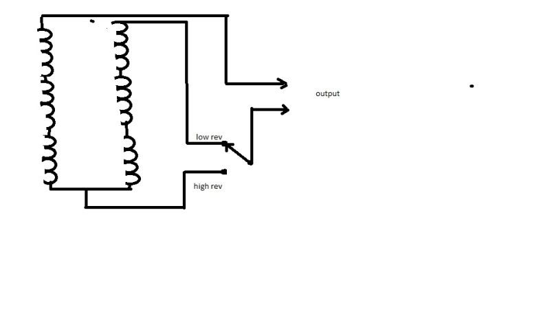
I'd wire it with heavier than stock wire and select the turn count to make it's output higher than stock. take your high output across all of the coils, and your low output across half of them. wind it so that all six coils produce desired voltage at low revs, and when you get spun up take your output across half the coils or some other number of your choosing. Heck you could even use a switch with more poles and have even more output options.
this doesn't show if the switch is a relay being controlled automatically or just a switch that the operator would control.
I think JB's stator with a good regulator is the way to go though.
-
DewCatTea-Bob
- Posts: 2897
- Joined: Sun Nov 01, 2009 10:53 am
- Location: Near SE side of Lake Michigan
Re: six coil alternator in a narrow case 250
" If I were inclined to have a dual output from my alternator I'd consider wiring it like this insetad of having two independant different sets of coils.
this doesn't show if the switch is a relay being controlled automatically or just a switch that the operator would control. "
____ That's a fairly logical set-up Mike, and quite similar to what many Jap-bikes have had, except they have it so that the optional bank of additional coils are much greater than the bank that's always left connected. _ And the switch you show is incorporated along-with the light-switch.
__ That is just one of the many possibilities that I've meant to cover for how the wide-case alt.wire-leads may be connected up, (however not the choice I'd most recommend) !
____ Your notion of flipping the switch depending on RPM is of course quite logical... Perhaps a relay-trigger set-up could be devised so that the auto-advancer could trigger the switch depending on the AAU's position.
Although I-myself would still prefer to use an ammeter and a manual-switch, so as to best control when the extra power is allowed into the system.
" I'd wire it with heavier than stock wire and select the turn count to make it's output higher than stock. "
____ So then you expect to have your cake & eat it too, so your core-coils would become extra fat ? _ I don't see how you could expect to be sure to have the room/space to have BOTH thicker windings PLUS more turns (of coil-loops) !? _ Perhaps you expect to reduce the thickness of the coil-cores (so as to create the needed extra space for your heftier windings) ?
__ And also, I see no reason to go to a heavier-gauge, if at the same time you expect to convert to 12-volts,, (unless intending to merely have a more robust 6-volt system).
" I think JB's stator with a good regulator is the way to go though. "
____ Probably so, if yar not one who's bent on getting every drop of power-juice possible. _ That his set-up full-wave rectifies the total available alt.power-output, means his charging-system is (at least) about double that of the stock 6-pole n-c set-up.
____ I've altered the drawing to better represent how the extra alt.winding would be switched, Jap.bike style.
One alt.winding is always connected to the rectifier, while the other is switched (along with the light-switch). _ They logically did it that way so as to make life easier on the voltage-regulator, (as the light-load helped the regulator manage the extra alt.power-output).
The red-wire is the common, (not grounded).
Fun-Cheers,
-Bob
You do not have the required permissions to view the files attached to this post.
PLEASE NOTE... If this-post is not-yet signed-off with '-Bob', then I'm still in the process of completing it,, and if not also included with 'DCT' near bottom as well, then I may edit this post's wording at a later time. - Dct.Bob
-
jbcollier
- Posts: 86
- Joined: Sun Oct 10, 2010 2:30 am
Re: six coil alternator in a narrow case 250
Sorry, I have been busy and not back to the forum until now. The reason I use a 35w headlight as then I get the battery charging under 3000 rpm. Going to a 55w bulb means its not charging the battery until 5000 rpm. The difference in light output between 35w and 55w is, for practical purposes, none as neither is suited to high speed work at night. My mods have teased perhaps a genuine 80w (max) out of an old fashioned design. The 35w headlight and 35ishw ignition system (3 ohm coil, 1 ohm ballast and the Rita box optimized for lower dwell) chew up most of it up.
Quite frankly, if I was doing it again, I would simply buy one of the higher output options presently on the market. That way I could drive a xenon headlight (large start-up draw) and perhaps even a heated vest.
Quite frankly, if I was doing it again, I would simply buy one of the higher output options presently on the market. That way I could drive a xenon headlight (large start-up draw) and perhaps even a heated vest.
Return to “Ducati Singles Main Discussions (& How to Join)”
Who is online
Users browsing this forum: No registered users and 38 guests