Postby DewCatTea-Bob » Fri Jan 01, 2010 12:42 pm
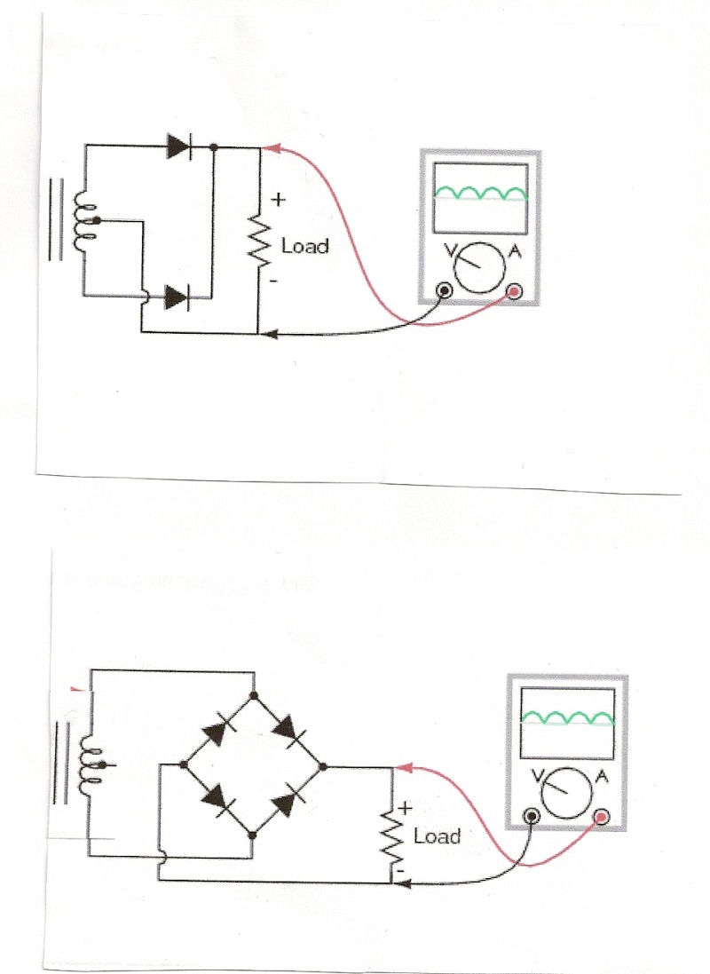
" i ditched the original full wave center tapped rectifier design "
____ Eldert, your two diagrams are both correct representations of your 'before & after', (although the diagram which is supposed to represent the stock set-up, shows it's 2 diodes facing backward!).
__ However the stock rectifier-unit is not "full wave",, it's more like 'dual half-wave', (as 4 diodes are required for full-wave rectification, and the original-unit has only two power-diodes)!
"and went for a full wave bridge type rectifier and did
not use the center tap ( the red wire ) only the 2 yellow wires are used with this setup "
____ Right, that's the easiest (& cheapest) way to convert to a 12-volt system!
The downside to not making any use at all of the RED-wire-lead, is that if you run at high-RPMs with lights off, your voltage-regulator will be overworked, and many such regulators simply dump excess power-juice to ground, thus robbing power from your rear-wheel, while also over-heating the alternator, & reducing fuel-economy!
__ That's why I had mentioned before that I hope you don't use such a rect.reg-unit on the entire output -(between the two yellow-wires) of that "70-watt" alternator!
____ I know of several (more complicated) wiring-methods for taking full advantage of that alternator's capability, without as much waste.
I may get to posting details about that some time.
DUKE-Cheers,
-Bob
PLEASE NOTE... If this-post is not-yet signed-off with '-Bob', then I'm still in the process of completing it,, and if not also included with 'DCT' near bottom as well, then I may edit this post's wording at a later time. - Dct.Bob