n-c alternator modifications: discussion and testing
Moderator: ajleone
-
ecurbruce
- Posts: 317
- Joined: Fri Apr 01, 2011 12:43 am
- Location: Hurricane mills TN
Re: 6volt or 12 volt?
OK, Bob, good call, I didn' pay that much attention to the rotor poles themselves, which become magnetized. Is the end result the same?
-
wcorey
- Posts: 323
- Joined: Sun Jan 31, 2010 1:50 am
- Location: MA USA
Re: 6volt or 12 volt?
A round of half wave rectified tests, done at both 1 ohm and 3 ohm.
<EDIT> Note; the terms 'dual half wave' 'stock parallel' and 'full wave' 'stock parallel' are generally interchangeable for the intents and purposes of this and other tests.
I went back and audited/compared a few to past ones and most were fairly consistent, with some exceptions...
I caught an error in the ac output meter wiring/results from the past 'stock parallel' tests, was showing the ac as a much lower value than it should be. The ac meter is something that hasn't been included in any drawings and this is a perfect example of why I've needed complete drawings. And a perfect example of why I put up the pics, that's how I (and anyone else who cared to look for it) could see exactly where I screwed up. And why it's good to do the testing while I'm not half asleep...
Not sure if I should go back and correct the pics and info on the old posts as I'm not sure if there were other posts with comments pertaining to the off figures that would cease to make sense after said corrections. I'll just make note of the errors for now...
Another thing I may have f'ed up on some earlier tests is load resistance, this may account for a couple inconsistencies. At some point I can go back and figure it out by the pics and which resistors I was using, a couple of the original multi-resistor ensembles value figures are suspect...
Note to D-Bob (as opposed to B-Bob, now that he's also in this thread, lol); I think I have a bandaid solution for your cut off picture issue. Left click on the pic, then right click the first menu item, 'view image', it will toggle the broswer into a plain widow and not be subject the the size limitations of this site. Back arrow puts you right back...
Also, Bruce, nice work on the stator wiring breakdown, I'll have to show that to Ken-the-Physicist, might spark something as all he has now is my verbal description.
half wave series 1ohm 3450rpm, 3.7a 17.2vac, 3.8vdc
half wave series 3ohm 3450rpm, 2.6a, 23.6vac, 7.8vdc
half wave 'one side' 1ohm 3450rpm, 3.6a, 13.4vac, 3.7vdc
half wave 'one side' 3ohm 3450rpm, 1.8a, 15.2vac, 5.4vdc
half wave 'the other side' 1ohm 3450rpm, 3.6a, 13.3vac, 3.7vdc
half wave 'the other side' 3ohm 3450rpm, 1.8a, 15.2vac, 5.4vdc
'dual half wave' 'stock parallel' 1ohm 3450rpm, 6.6a, 21.6vac, 6.8vdc
'dual half wave' 'stock parallel' 3ohm 3450rpm, 3.6a, 29vac, 11vdc
Bill
Last edited by wcorey on Fri Jul 29, 2011 5:50 pm, edited 4 times in total.
-
wcorey
- Posts: 323
- Joined: Sun Jan 31, 2010 1:50 am
- Location: MA USA
Re: 6volt or 12 volt?
_____ I don't have the time (for the next 30-hours) to post a pic of the rotor with it's 6-poles showing,
Just happened to have one handy...
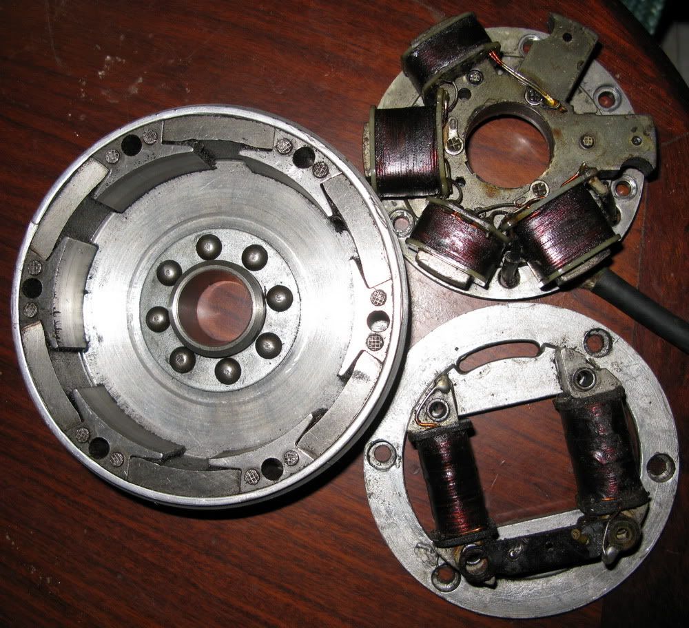
Bill
-
MotoMike
- Posts: 487
- Joined: Wed Aug 04, 2010 3:40 am
Re: 6volt or 12 volt?
Bill
thanks for the photo of the alternator rotor. Interesting design and I see what Bob was talking about.
thanks for the photo of the alternator rotor. Interesting design and I see what Bob was talking about.
-
DewCatTea-Bob
- Posts: 2897
- Joined: Sun Nov 01, 2009 10:53 am
- Location: Near SE side of Lake Michigan
Actual Magnetic-flux Source
By: ecurbruce...
" I didn' pay that much attention to the rotor poles themselves, which become magnetized. Is the end result the same? "
____ Not exactly sure what you're actually asking Bruce.
While we know that the magnets themselves are the original-source of the magnetic fields, the rotor-poles effectively bend the magnetic-flux from the North & South ends of the magnets so that the strength of the flux-field is redirected towards the ends of the stator-core, (which in turn are briefly like-magnetized, to then energize the coils).
I believe it's fairly certain that the magnetic-flux which does the actual work, is not at the same strength-density as it is right-at the magnets themselves, (and that would no doubt still remain the case, even if the loss due to the space-gap between the rotor-poles & stator poles could be reduced to zero).
I'm fairly certain that the metal/iron-alloy used in the rotor-poles is incapable of maintaining & passing-on the same amount of magnetic-flux density of that of the magnets themselves, however since each rotor-pole get's it's strength from the ends of TWO magnets, I'd figure the resulting strength of the flux-field at a rotor-pole, is still fairly near that which is found at the end of one magnet.
__ I've added a picture of the alt.rotor, (so as to show it's 6 poles), to my prior post (which had mentioned that I didn't have time to include one, at the time when I placed that post).
Dukaddy-DUKEs,
-Bob
PLEASE NOTE... If this-post is not-yet signed-off with '-Bob', then I'm still in the process of completing it,, and if not also included with 'DCT' near bottom as well, then I may edit this post's wording at a later time. - Dct.Bob
-
MotoMike
- Posts: 487
- Joined: Wed Aug 04, 2010 3:40 am
Re: 6volt or 12 volt?
There are a lot of ways to build a permanent magnet alternator. In some I have studied a long time ago, the magnet is positioned with it’s north or south pole close to the coil. In some of these the other end goes unused. The method employed here by the Ducati engineers is clever but probably fairly common.
I think that one function of cores is to get the flux to the coil where producing magnets in the needed shape to get them close to the coils is not practical. But more importantly the cores not only bend or direct the magnetic lines of flux, they concentrate it. So my guess would be that they are more efficient than the magnet alone.
And as Bob has mentioned the cores should not be easily magnetized as they are made of soft material that allows the magnetic domains to be easily switched, essentially with the changing direction of the magnetic fields.
Mike
-
ecurbruce
- Posts: 317
- Joined: Fri Apr 01, 2011 12:43 am
- Location: Hurricane mills TN
Re: 6volt or 12 volt?
The manufacurers of speaker drivers have taken the concentration of magnetic flux to a high level, if you've ever played with the magnet on the back of a speaker, the core is alot stronger magnet than the magnet itself that surrounds the core.
-
DewCatTea-Bob
- Posts: 2897
- Joined: Sun Nov 01, 2009 10:53 am
- Location: Near SE side of Lake Michigan
Bill's latest Alt.power Testing Outcome/Results
By: wcorey...
" A round of half wave rectified tests, done at both 1 ohm and 3 ohm. "
____ Okay, thanks a lot for all the extra testing, Bill !
" I caught an error in the ac output meter wiring/results from the past 'stock parallel' tests, was showing the ac as a much lower value than it should be. The ac meter is something that hasn't been included in any drawings and this is a perfect example of why I've needed complete drawings. And a perfect example of why I put up the pics, that's how I (and anyone else who cared to look for it) could see exactly where I screwed up. "
____ The AC readings are not of great importance once we've included rectification-circuits, and may only provide possible help with figuring-out what's actually going-on.
The AC-meter was most-always to be kept connected across the tested alt.winding, so I wonder exactly how you believe you had done any error, so as to have "screwed up" ?
" Not sure if I should go back and correct the pics and info on the old posts as I'm not sure if there were other posts with comments pertaining to the off figures that would cease to make sense after said corrections. I'll just make note of the errors for now... "
____ Right, don't go-back & change anything,, (cuz you may have those things actually correct, as they already are,, and even mistaken tests may provide useful info).
If you still think you have an error-correction to make, then please let us know exactly what it is, before-hand !
" Another thing I may have f'ed up on some earlier tests is load resistance, this may account for a couple inconsistencies. At some point I can go back and figure it out by the pics and which resistors I was using, a couple of the original multi-resistor ensembles value figures are suspect... "
____ While it could be useful to know exactly what the actual resistances were for each test, it's not real important for figuring the wattage-output (which was the main concern).
____ Now concerning this (common series-type) test-scheme...
" half wave series 1ohm 3450rpm, 3.7a 17.2vac, 3.8vdc "
half wave series 3ohm 3450rpm, 2.6a, 23.6vac, 7.8vdc "
____ That's only 14.0-watts with the 1-ohm load, and 20.3-watts with the 3-ohm load,, with both alt.windings connected in the std.series arrangement.
Obviously, the GREATER the load's power-consumption, the LESS total-wattage the alternator offers to produce, (in THIS series arrangement).
____ Next, concerning this (half of stock, power-circuit) test-scheme...
" half wave 'one side' 1ohm 3450rpm, 3.6a, 13.4vac, 3.7vdc
half wave 'one side' 3ohm 3450rpm, 1.8a, 15.2vac, 5.4vdc "
...
" half wave 'the other side' 1ohm 3450rpm, 3.6a, 13.3vac, 3.7vdc
half wave 'the other side' 3ohm 3450rpm, 1.8a, 15.2vac, 5.4vdc "
____ That's 13.3-watts with the 1-ohm load, and 9.7-watts with the 3-ohm load,,
using just one of the alt.windings, (1-4 or 2-3), EITHER winding all on it's own & alone.
____ Next, concerning this stock-like test-scheme...
" half wave 'stock parallel' 1ohm 3450rpm, 6.6a, 21.6vac, 6.8vdc
half wave 'stock parallel' 3ohm 3450rpm, 3.6a, 29vac, 11vdc "
____ That's nearly 45-watts for the combined half-wave rectified outputs of both alt.windings working together in stock parallel-fashion, with the 1-ohm load,,
and 39.6-watts with the 3-ohm load.
__ This test-outcome, (if I'm not mistaking), is far greater than Bill's previous (and supposedly identical) tests of this stock-like scheme. _ Cuz BEFORE, the expected combined output of both alt.windings together added-up to well LESS than their expected added-total, (which was an unexpected surprise & disappointment to me!), (and that test-outcome was helping to lead me to think that perhaps Ducati may not have realized what they were actually doing).
Now this-time, I'm also surprised, but in the opposite way ! ...
Here (as always), I expected that the 13.3-watts from EACH alt.winding would naturally provide a total power-output of near (the expected) 26.5-watts,, however but instead, Bill managed to get a (somewhat magical) near 45-watts !
__ I'm thinking that if THIS test is all done correctly, then it's more than likely that the 'push-back' reduction-effect which tends to kill-down power-output in the non-stock 'series' arrangement, actually HELPS liven-up the power-output in the stock-type arrangement. _ And so I'm beginning to think that each winding thus provides a WORTH-WHILE (forward!)- kick to the other, in a complimentary manor as if the going-dead/opposite-winding provides further magnetic-charging, (beyond that from just the magnets alone), of the stator-poles, so as to assist in providing added magnetic-flux for the alt.winding which happens to just be coming-to-life (with it's own turn to provide the next pulse of DC-power).
I've mentioned this probable effect before (as "PULL/PULL"), but didn't expect the complimentary-effect to be so effective !
__ Whatever the actual cause of this unexpectedly high test-outcome, it needs to be further investigated & ironed-out !
____ Next we can make some note-worthy notes from this batch alone, of Bill's testing.....
__ First, (from the first presented ['series'] test), we ought note that with the non-stock method of the simple 'series' connection (of both alt.windings together), the power-output falls-off downward as the demand for power increases, (not desirable!),, (while compared to either alt.winding alone, power-output [logically]- INCREASES as the power-load increases [with the lower-value of load-resistance]).
__ This quite disappointing outcome for this non-stock but commonly-done 'series' arrangement (of the two alt.windings connected together end-to-end), seems to produce ONLY a slight bit more max.power-output than either alt.winding alone all by one's self. _ (Which is a pretty-good indication that the alt.stator could be rewound in another/non-stock fashion, so as to better obtain the full possible strength which ought to be available from the 6-pole stator.)
__ This is another test which confirms that the two individual alt.windings arranged in 'std.series' combination, do not combine (as would normally be expected), to provide their individual power-outputs as if directly ADDED together !
____ Next, Bill's testing of each alt.winding alone separately, indicates that near 3500-RPM, each power-output is only about 13 to 14 watts, and if both added together, (not in an "instant of time" of-course!), resulted in the normally expected sum of 27-watts, then the stock 'break-even' RPM-point would not have been reached by then (with such a 1-ohm running-load) ! _ Yet (as I think I recall now), the stock-system breaks-even near 3k-RPM. _ So it now remains questionable as to whether a max.power-output of just 27-watts is only what the stock charging-system ought provide (near 3500-RPM). _ (While Bill's previous [3450]- test-outcome/results [indicating even less power !], must more-certainly be insufficient to reflect the true stock power-output.)
(However, with Bill's latest test-results of near 45-watts, that would be more like what should be expected, in accordance with the stock break-even RPM-point.)
____ And next, with the quite non-disappointing test-outcome results which Bill has now most recently obtained with the stock parallel/twin (alt.winding with dedicated diode) circuit setup,, it seems obvious that the best-way to get the most power out of the stock alternator, is to avoid the commonly done 'series' connected alt.winding arrangement, and instead stay-with the stock parallel/twin-diode setup, (regardless of 6 or 12 volt system).
Cuz it seems that the Ducati 6-pole alt.stator has been specially-wound to function in a very-special & positive way,, and to reconnect it's alt.winding lead-ends in any other manor, not only looses the special-effect's unique 'pull-pull' function, but also can possibly be set up to function in an opposite manor from that which Ducati apparently had intended.
____ I'm still sure however, that the alt.stator could be re-wound in a more conventional manor, so as to obtain the doubled power-output that's been normally expected from the series-connected alt.winding arrangement/setup.
__ With the same 288 coil-turns (around the stator's 4 core-coils), someone (like Bruce) ought to be able to obtain about 53-watts -(the 13.3w x 2 x 2) at the 3450-RPM, (with full-wave rectification).
And with a third-pair of coil-spools (with their 144 additional coil-turns), the power-output ought increase to about 80-watts, near that 3450-RPM point. _ But I sure would-not recommend doing that (as one continuous stator-winding) ! _ Rather, I'd choose to keep one pair of core-coils connected to the charging-system at all times, and only connect the other two pairs just when the lights are turned-on.
Fun-Cheers,
-Bob
PLEASE NOTE... If this-post is not-yet signed-off with '-Bob', then I'm still in the process of completing it,, and if not also included with 'DCT' near bottom as well, then I may edit this post's wording at a later time. - Dct.Bob
-
MotoMike
- Posts: 487
- Joined: Wed Aug 04, 2010 3:40 am
Re: 6volt or 12 volt?
Bob wrote:_ I'm still sure however, that the alt.stator could be re-wound in a more conventional manor, so as to obtain the doubled power-output that ought be expected from the series-connected alt.winding arrangement/setup.
MM
I concur and with info from Bruce, we see that the counts are not that high and certainly within the ability of most of us to do by hand. I look forward to that test.
MM
I concur and with info from Bruce, we see that the counts are not that high and certainly within the ability of most of us to do by hand. I look forward to that test.
-
wcorey
- Posts: 323
- Joined: Sun Jan 31, 2010 1:50 am
- Location: MA USA
Re: 6volt or 12 volt?
Some new stuff, a little change in presentation, I have the pics if anyone feels the need...
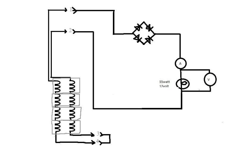
Note; Full wave, ‘stock parallel’, can be otherwise/also known as 'Dual half wave', 'stock parallel'...
Full wave, ‘stock parallel’, 5ohm 3450rpm-----------2.4a, 30.4vac, 12vdc,-----28.8w
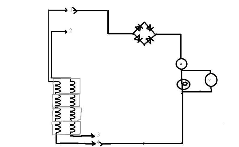
Full wave, Series, 5ohm 3450rpm---------------------3.4a, 21.2vac, 17vdc------57.8w
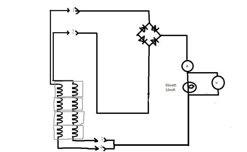
Full wave, Single winding, 5ohm 3450rpm-----------2.3a, 14.7vac, 11.4vdc----26.2w
Full wave, ‘stock parallel’, 3ohm 3450rpm----------3.6a, 28.7vac, 10.9vdc-----39.2w
Full wave, Series, 3ohm 3450rpm--------------------4.1a, 16.2vac, 12.5vdc-----51.2w
Full wave, Single winding, 3ohm 3450rpm----------3.4a, 13.7vac, 10.3vdc------35w
Full wave, Series, 2ohm, 3450 rpm----------------- 4.5a 12.7vac, 9.6vdc-------43.2w
Full wave, ‘stock parallel’, 1ohm 3450rpm---------6.5a, 21.6vac, 6.7vdc-------43.5w
Full wave, Series, 1ohm 3450rpm-------------------4.9a, 8vac, 5vdc-------------24.5w
Full wave, Single winding, 1ohm 3450rpm---------6.3a, 9.7vac, 6.5vdc---------40.9w
Bill
Note; Full wave, ‘stock parallel’, can be otherwise/also known as 'Dual half wave', 'stock parallel'...
Full wave, ‘stock parallel’, 5ohm 3450rpm-----------2.4a, 30.4vac, 12vdc,-----28.8w
Full wave, Series, 5ohm 3450rpm---------------------3.4a, 21.2vac, 17vdc------57.8w
Full wave, Single winding, 5ohm 3450rpm-----------2.3a, 14.7vac, 11.4vdc----26.2w
Full wave, ‘stock parallel’, 3ohm 3450rpm----------3.6a, 28.7vac, 10.9vdc-----39.2w
Full wave, Series, 3ohm 3450rpm--------------------4.1a, 16.2vac, 12.5vdc-----51.2w
Full wave, Single winding, 3ohm 3450rpm----------3.4a, 13.7vac, 10.3vdc------35w
Full wave, Series, 2ohm, 3450 rpm----------------- 4.5a 12.7vac, 9.6vdc-------43.2w
Full wave, ‘stock parallel’, 1ohm 3450rpm---------6.5a, 21.6vac, 6.7vdc-------43.5w
Full wave, Series, 1ohm 3450rpm-------------------4.9a, 8vac, 5vdc-------------24.5w
Full wave, Single winding, 1ohm 3450rpm---------6.3a, 9.7vac, 6.5vdc---------40.9w
Bill
Last edited by wcorey on Fri Jul 29, 2011 5:51 pm, edited 4 times in total.
Return to “Ducati Singles Main Discussions (& How to Join)”
Who is online
Users browsing this forum: No registered users and 38 guests