LED taillights on a motorcycle with an AC electrical system
The problem:
Some of us with old motorcycles have AC (Alternating Current.)
electrical systems. That means the current flowing through the wires
(amps) alternately change direction many thousands of times a minute.
For the purposes of this topic we might as well regard the AC electrical system as
an 'alternating voltage' system since it's easier to grasp that concept.
The voltage in an AC system is also unregulated, meaning the voltage at the
extreme peaks of the sinusoidal AC voltage wave
(its positive and negative peaks) often climbs with engine RPMs.
Light bulbs (not LEDs) are considered "non-polarized" which means they don't care what
polarity the voltage is or what direction current flows through them.
Light bulbs will work in positive voltage systems or negative voltage systems,
as well as in AC systems where the voltage polarity is constantly alternating
polarities between positive and negative.
Light bulbs can be dim at low RPMs, they are susceptible to failure from
vibration and so sometimes we would like to "upgrade" to higher brightness and
more robust LED lighting in our taillights.
However, LEDs (Light Emitting Diodes) are "polarized" and only run off of DC voltage. Often times when the voltage of the motorcycle reverses
direction, the reversed and unregulated negative voltage suddenly applied to the
LED will make the LED fail. Most LED taillights are designed to use
positive DC voltage.
(Only some old British cars and motorcycles used negative DC voltage and
those vehicles are said to have a "positive ground system." We will not
cover positive ground systems in this discussion.)
Simplest to install and cheapest LED adaptation to an AC
motorcycle:
Most everyone has a negative ground vehicle so this narration presumes
negative ground.
The simplest and cheapest way to implement a LED taillight on
a AC bike is to half-wave rectify the AC voltage into DC voltage. In this simple adaptation there is no attempt to regulate the voltage, only to
rectify its polarity from AC to DC. Regulation would require more
components and would serve to control the maximum voltage.
Why regulate? Similar to reverse voltage, too much voltage can also burn out LEDs.
But for simplicity's sake we will not try to regulate the voltage at this time.
The simplest rectifier is a "half-wave rectifier," Effectively half the
power available is thrown away in a half-wave rectifier by blocking the half of the
AC system's voltage sine wave. The resulting power that comes out of
the half-wave rectifier is referred to as pulsating DC voltage because the DC
will pulse on and off at a very high rate of speed.
A power diode is used to rectify the AC into DC voltage, but the power diode
has to be installed in the correct direction so that the pulsating DC voltage
becomes positive DC voltage and not negative DC voltage.
A single power diode might cost around a dollar.
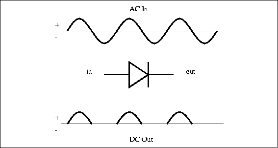
Basic half-wave rectifier concept:
We want to run the LED taillight off of positive DC voltage.
The thin line in the following top and bottom diagrams represents your
motorcycle's frame which, because it is metal, is used just like a wire in the
wiring harness. It serves as your voltage reference point, or
"ground."
 |
|
In the drawing labeled "AC in" The thick line represents the voltage on the
wire going to your running light or to your brake light. It climbs into
the + (positive voltage) region, changes direction and then swings down into the -
(negative voltage) region with respect to your motorcycle's frame over and over again..
The triangular symbol represents the power
rectifier diode you will be installing.
In the drawing labeled "DC out" The thick line represents
how the voltage on the
wire going to your running light or to your brake light will appear after
rectification. The voltage climbs into the + (positive) region and returns
to 0 volts, then after a while it repeats again, always and only in the positive
region. This is what the LED wants to see: DC voltage.
|
Implementation:
I hate the thought of soldering wires to the two ends of a diode, wrapping
the whole thing with electrical tape or putting heat-shrink tubing around it,
and being left with a lumpy-looking aberration in the wiring harness.
Electrical
tape unravels over time and lets water gets in, and sticky tape residue will haunt
the wires forever.
While the connection to the diode may be electrically secure, is it
mechanically solid?
While the rectifier diode is hidden in the wiring harness, I know it's there,
and I have higher standards than most considering I am sort of 'in the business'
of automotive and motorcycle wiring.
To make a compact, fully insulated, rugged, water-resistant and electromechanicaly
solid "in-the-line" half wave rectifier I used a 1N5402 power diode
available from Radi0 Shack at a cost of about $2 for two
diodes.
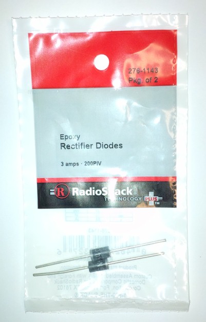
The term "200PIV" means the diode will resist up to 200 volts of
inverse voltage, far more than is needed.
LEDs use very little forward current so the 3-amp rating is also far more
than is needed to run a LED taillight, but I chose this diode for its body diameter.
The reason for this will become clear very quickly.
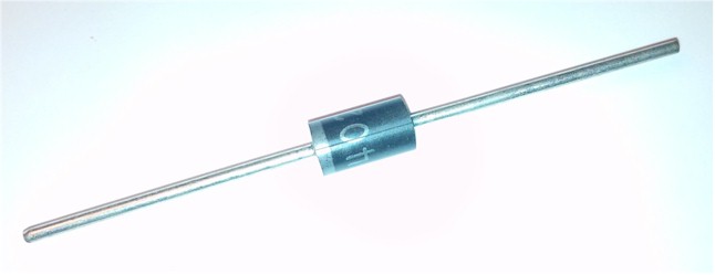
Note the light-colored band at one end of the diode. That's the
"cathode" of the diode. It's important later.
You'll also need one each of the fully insulated blue-colored .(14-16 AWG)
male and female .250 " Quick Disconnect terminals.
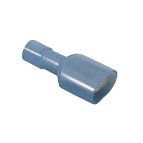
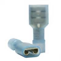
Male
Female
The 14-16 AWG size fully insulated terminals are important because the
largest wire
diameter they are made to accept is about the same as the outer diameter of the
diode.
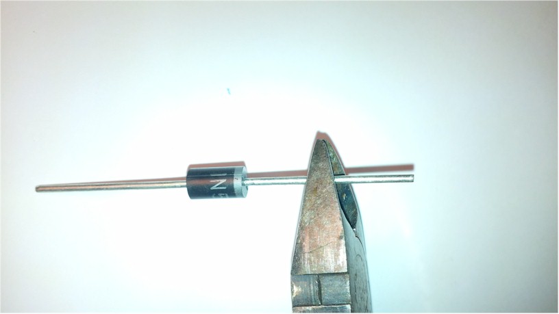
Clip the ends off the power diode's legs to about 3/8".
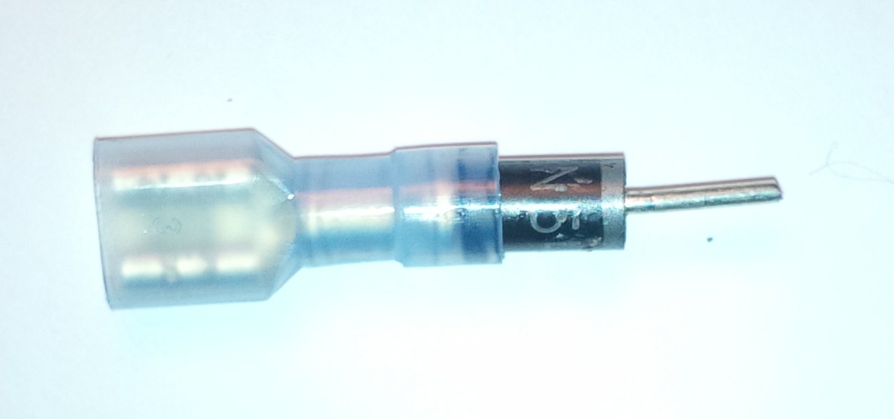
Push the actual body of the diode into the wire opening of the Quick
Disconnect terminals.
This is what the assembly should look like. You can still see the
cathode band through the opaque insulation on the connector; in my case the
cathode connects to the Male .250 terminal.
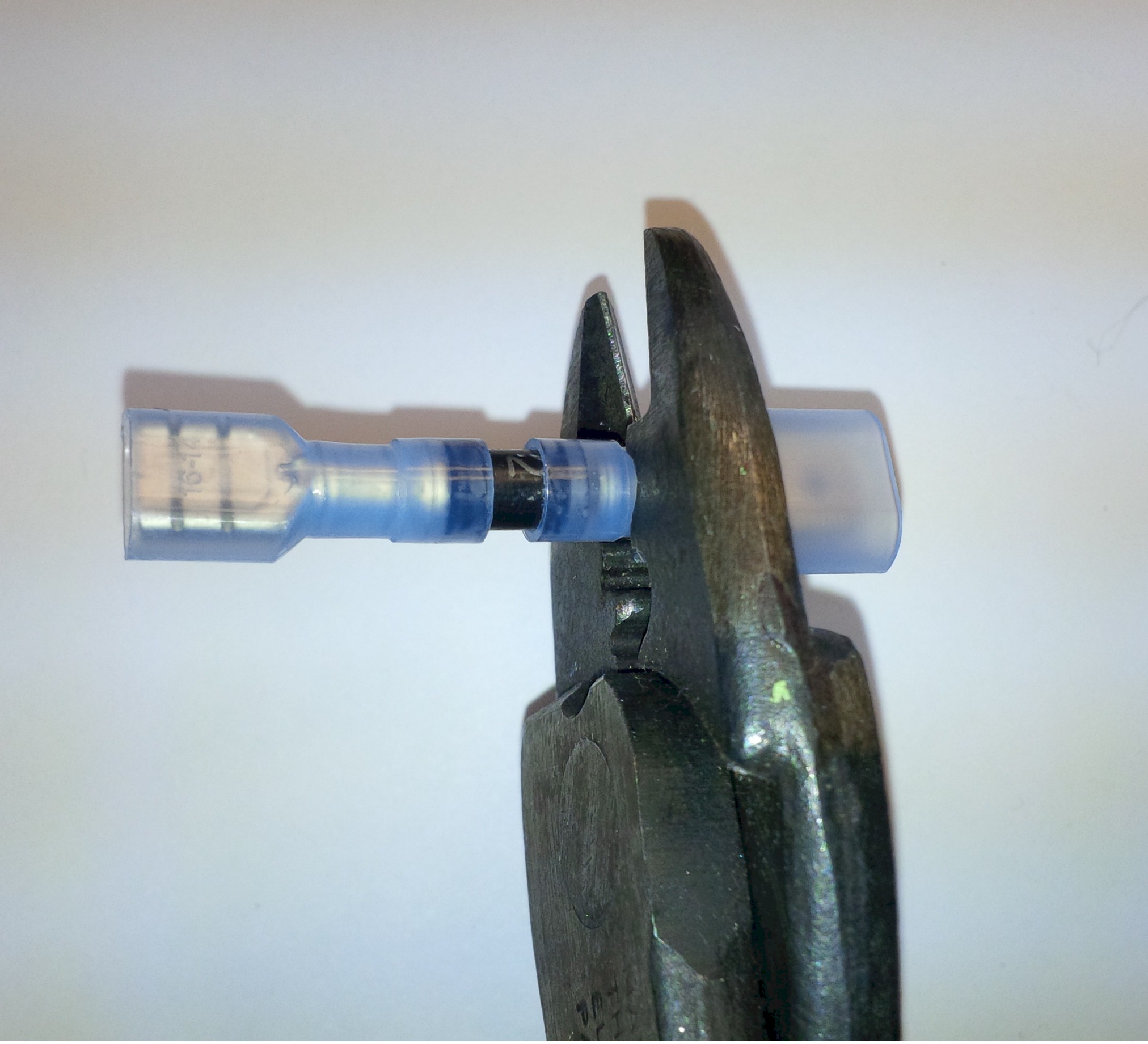
Crimp each terminal in the narrowest portion of the terminal to make a strong
electrical connection. The assembly is done.
No soldering required!
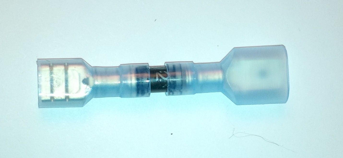
When you go to install this diode assembly you merely cut the wire that needs
the diode and put a fully insulated male and female disconnect on the two ends
of the cut wire. You'll need to plan which end of the cut wire should get the
male terminal and which should get the female terminal based on what terminal
you put on the cathode of the diode and which way the diode will be facing when
inserted between the cut wire. That will be covered soon.
Now you'll be able to install the half-wave rectifier power diode in-line quickly, and should you ever need
to remove the diode you can take it out just as quickly and rejoin the cut wires
by pushing the wire's connector's together.
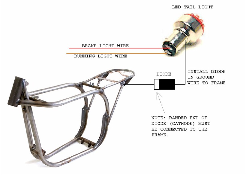
One power diode or two?
My taillight is in a fiberglass tailpiece, as such the tailpiece is not
electrically conductive. That means I have to run a wire from the
taillight bulb socket's metal shell to the motorcycle's frame. For this
reason I am able to use a single poser diode for half-wave rectification.
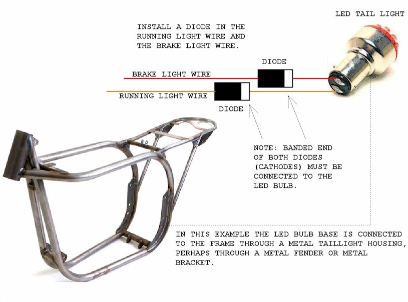
If your taillight is mounted in a metal fender or in a metal bracket, that is
to say that your wiring harness has only two wires going to the taillight; one
for the brake light and one for the running light, with no third wire connecting
the bulb socket to the motorcycle's frame, you will need to use two power diodes
for half-wave rectification.
Single diode implementation for nonconductive (fiberglass,
plastic) mounted taillights:
Dual diode implementation for taillights inherently
connected through metal to the motorcycle's frame.
If you ever have to return to incandescent light bulbs,
pull out the diode(s) using the quick disconnect terminals and that should leave
a male and a female disconnect terminals on opposite sides of the wire such that
the wire connection can be immediately reinstated using the remaining .250
terminals.
Caveat:
On my Ducati AC electrical system motorcycle the brake lamp filament grounds
the ignition coil to the frame through the brake light switch when the brake
pedal is depressed. I know it sounds bizarre but it's true. It's too
complicated to explain here unless a lot of people start asking.
If you do this conversion and you step on the rear brake pedal and the engine
dies, you'll know what I am talking about.
When performing this conversion I had to:
A) ground the ignition coil directly to the frame,
and
B) change the brake light switch from a SPST (Single Pole Single Throw) NC
(Normally Closed) to a SPST NO (Normally Open),
and
C) connect the "input" side of the brake light switch to the running light circuit.
How can you tell in advance if switching to LEDs is going to kill the engine
when you step on the brake?
Pull the brake light bulb out of its socket and while your motorcycle is on
the center stand and the engine is running depress the brake pedal. If the engine dies you're
in for steps A, B and C. If the engine continues to run you shouldn't need
to perform steps A, B and C, Be
sure to replace the brake light bulb before you ride the motorcycle.
Disclaimer:
Half-wave rectification may not by itself be sufficient to power an LED
taillight from an AC system. As was mentioned, there is no voltage
regulation occurring with this simple rectification.
Simple LED taillights contain biasing resistors to set the amount of
current that will flow through the LEDs, and the biasing resistor's value
assumes a fixed voltage level, such as a constant 12 volts or constant 6 volts.
When the pulsating DC is below the expected voltage the LED will not light
to full intensity. When the pulsating DC voltage is above the expected
voltage level the current passing through the LEDs could be enough to damage,
shorten the life span or burn out the LEDs.
What might help is that during half-wave rectification the LED is
un-powered 50% of the time giving the LED a chance to cool down. For some
portion of the pulse the voltage will be below the bias resistor's optimal
voltage level. Any over-voltage condition will be very short lived, and it
might not do any damage to the LEDs.
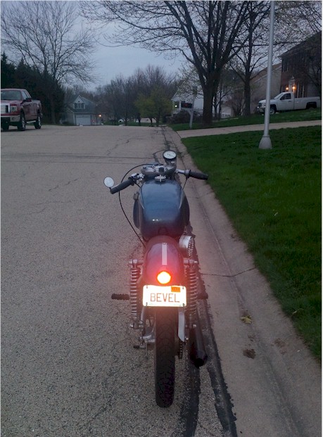
Always check your brake and taillight often. I usually check mine
every time I get on my motorcycle and when I get off it.
My half-wave rectifier is working to power my LED taillight without
voltage regulation, but I am using a rather high-end LED product that has
integral current limiting to power its LEDs:
 Franzen@CuLayer.com
This page might later be expanded to cover such subjects as simple and cheap
as possible voltage regulation, and perhaps full wave rectification.